IMAQ ™ IMAQ PCI-1428 User Manual High-Quality Camera Link Image Acquisition Device for PCI IMAQ PCI-1428 User Manual January 2002 Edition Part Number 322862B-01
Support Worldwide Technical Support and Product Information ni.
Important Information Warranty The IMAQ PCI-1428 is warranted against defects in materials and workmanship for a period of one year from the date of shipment, as evidenced by receipts or other documentation. National Instruments will, at its option, repair or replace equipment that proves to be defective during the warranty period. This warranty includes parts and labor.
Compliance FCC/Canada Radio Frequency Interference Compliance* Determining FCC Class The Federal Communications Commission (FCC) has rules to protect wireless communications from interference. The FCC places digital electronics into two classes. These classes are known as Class A (for use in industrial-commercial locations only) or Class B (for use in residential or commercial locations). Depending on where it is operated, this product could be subject to restrictions in the FCC rules.
Canadian Department of Communications This Class B digital apparatus meets all requirements of the Canadian Interference-Causing Equipment Regulations. Cet appareil numérique de la classe B respecte toutes les exigences du Règlement sur le matériel brouilleur du Canada. European Union - Compliance to EEC Directives Readers in the EU/EEC/EEA must refer to the Manufacturer's Declaration of Conformity (DoC) for information** pertaining to the CE Mark compliance scheme.
Conventions This manual uses the following conventions: <> Angle brackets that contain numbers separated by an ellipsis represent a range of values associated with a bit or signal name—for example, DBIO<3..0>. » The » symbol leads you through nested menu items and dialog box options to a final action. The sequence File»Page Setup»Options directs you to pull down the File menu, select the Page Setup item, and select Options from the last dialog box.
Contents Chapter 1 Introduction About the IMAQ PCI-1428 ...........................................................................................1-1 Camera Link ..................................................................................................................1-2 Overview .........................................................................................................1-2 Interfacing with the PCI-1428 ...................................................................................
Contents Start Conditions............................................................................................... 3-5 Acquisition Window Control .......................................................................... 3-6 Serial Interface ................................................................................................ 3-6 Chapter 4 Signal Connections Connectors.....................................................................................................................
1 Introduction This chapter provides an overview of the PCI-1428 image acquisition device, the Camera Link standard, Camera Link/PCI-1428 interfacing guidelines, and your software programming choices. About the IMAQ PCI-1428 The PCI-1428 is a highly flexible IMAQ device that supports a diverse range of Camera Link-compatible cameras from various camera companies. The PCI-1428 acquires digital images in real time and stores the images in onboard frame memory or transfers them directly to system memory.
Chapter 1 Introduction Easily synchronizing several functions to a common trigger or timing event is a common challenge with image acquisition devices. The PCI-1428 uses the Real-Time System Integration (RTSI) bus to solve this problem. The RTSI bus uses National Instruments RTSI bus interface and ribbon cable to route additional timing and trigger signals between the PCI-1428 and up to four National Instruments DAQ, motion control, or IMAQ devices.
Chapter 1 Introduction These variable parameters are defined on a per-camera basis in a camera file (camera_model.icd) supplied by National Instruments. The NI-IMAQ driver software uses the information in this camera file to program the PCI-1428 to acquire images from a specific camera. Without this camera file, the driver does not have the information necessary to configure the PCI-1428 for acquisition.
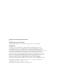
Chapter 1 Introduction Vision Software IMAQ Vision Image Analysis Blob Analysis Pattern Matching Color Matching and Analysis Filters Gauging and Measurement Display and ROI Morphology Application Software Measurement Studio (LabWindows/CVI, Visual C++, Visual Basic) LabVIEW NI-IMAQ IMAQ Driver Software NI-DAQ Hardware DAQ NI-Motion ValueMotion/ FlexMotion Figure 1-1. The Relationship between the Programming Environment, NI-IMAQ, and Hardware IMAQ PCI-1428 User Manual 1-4 ni.
Chapter 1 Introduction NI-IMAQ Driver Software The NI-IMAQ driver software is included with your IMAQ device. NI-IMAQ has an extensive library of functions you can call from your application programming environment. These functions include routines for video configuration, image acquisition (continuous and single-shot), memory buffer allocation, trigger control, and device configuration, as shown in Figure 1-2.
Chapter 1 Introduction National Instruments IMAQ Vision IMAQ Vision is an image acquisition, processing, and analysis library of more than 200 functions for grayscale, color, and binary image display, image processing, pattern matching, shape matching, blob analysis, gauging, and measurement. For unique image processing, you can use IMAQ Vision functions individually or in combination.
Chapter 1 Introduction IMAQ Vision Builder Prototype Builder File Vision Application Development IMAQ Vision IMAQ Vision LabVIEW Application Software Figure 1-3. IMAQ Vision Builder and Application Development Tools Integration with DAQ Any platform that supports NI-IMAQ also supports NI-DAQ and a variety of National Instruments DAQ devices, allowing your IMAQ device and NI-IMAQ development to integrate with National Instruments DAQ products.
2 Installation This chapter contains a list of necessary and optional items for getting started acquiring images with your IMAQ device. This chapter also explains how to unpack, configure, and install your IMAQ device.
Chapter 2 Installation Optional Equipment National Instruments offers a variety of products for use with the PCI-1428, including the following: • MDR 26-pin Camera Link cable from 3M for Base configuration • IMAQ D6804 breakout cable (for external triggering only) • RTSI bus cables for connecting the PCI-1428 to other IMAQ, motion control, or DAQ devices • Other National Instruments DAQ devices for enhanced triggering, timing, or input/output For more specific information about these products, ref
Chapter 2 Installation Read the Getting Started with Your IMAQ System document and the NI-IMAQ release notes to install your NI-IMAQ software, IMAQ hardware, and documentation. Configure your hardware using Measurement & Automation Explorer and online help. LabVIEW Read: • The section in chapter 4 in the NI-IMAQ User Manual for information on using LabVIEW with your IMAQ hardware.
Chapter 2 Installation Unpacking The PCI-1428 ships in an antistatic package to prevent electrostatic discharge from damaging board components. To avoid such damage in handling the board, take the following precautions: • Ground yourself via a grounding strap or by holding a grounded object, such as your computer chassis. • Touch the antistatic package to a metal part of your computer chassis before removing the board from the package.
Chapter 2 Installation instructions. All covers and filler panels must be installed while operating the device. Do not operate the device in an explosive atmosphere or where flammable gases or fumes may be present. Operate the device only at or below the pollution degree stated in the specifications. Pollution consists of any foreign matter—solid, liquid, or gas—that may reduce dielectric strength or surface resistivity. Pollution degrees are listed below.
Chapter 2 Installation measurements on household appliances, portable tools, and other similar equipment. • Installation Category I—for measurements performed on circuits not directly connected to mains1. Examples include measurements on circuits not derived from mains, and specially-protected (internal) mains-derived circuits. Figure 2-1 illustrates a sample installation. Figure 2-2. Sample Installation Installation You can install the PCI-1428 in any available PCI expansion slot in your computer.
Chapter 2 Installation 3. Follow the electrostatic discharge guidelines in the Unpacking section of this chapter. 4. Remove the computer cover. 5. Make sure there are no lit LEDs on the motherboard. If any are lit, wait until they go out before continuing installation. 6. Touch the metal part of the power supply case inside the computer to discharge any static electricity that might be on your clothes or body. 7.
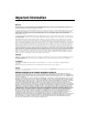
3 Hardware Overview This chapter provides an overview of PCI-1428 hardware functionality and explains the operations of the device’s functional units. Functional Overview The PCI-1428 features a flexible, high-speed data path optimized for receiving and formatting video data from Camera Link cameras. Figure 3-1 illustrates the key functional components of the PCI-1428.
Chapter 3 Hardware Overview Synchronous Dynamic RAM Enables Data Channel Link Receiver LUT LUT Data IMAQ SDRAM Data Interface PCI Interface and Scatter-Gather DMA Controllers Pixel Clock and Camera Enables Pixel Clock Camera Control Advanced Triggering and Timing Serial Control PCI Bus 26-Pin MDR Connector Data Acquisition, Scaling, ROI, and Control Differential Converter 68-Pin VHDCI UART Data Enables RTSI Bus Channel Link Receiver Pixel Clock External Triggers Figure 3-1.
Chapter 3 Hardware Overview configured in the camera file to generate precise timing signals for controlling digital camera acquisition. Base configuration includes the following bit allocations: • 8-bit × 1, 2, and 3 taps (channels) • 10-bit × 1 and 2 taps • 12-bit × 1 and 2 taps • 14-bit × 1 tap • 16-bit × 1 tap • 24-bit RGB Medium Configuration The PCI-1428 supports the 8-bit × 4 tap of the Camera Link Medium configuration. The Medium configuration requires using both connectors.
Chapter 3 Hardware Overview Multiple-Tap Data Formatter Many digital cameras transfer multiple taps, or channels, of data simultaneously to increase the frame rate of the camera. However, the data in each tap may not be transferred in the traditional top-left to bottom-right direction. Also, the taps may not transfer data in the same direction. The multiple-tap data formatting circuitry on the PCI-1428 can reorder the data from up to four taps.
Chapter 3 Hardware Overview duration of these signals in easy-to-use units. See the Interfacing with the PCI-1428 section in Chapter 1, Introduction, for information on camera files. Acquisition, Scaling, ROI The acquisition, scaling, and region-of-interest (ROI) circuitry monitors incoming video signals and routes the active pixels to the multiple-tap data formatter and SDRAM. The PCI-1428 can perform ROI and scaling on all video lines and frames.
Chapter 3 Hardware Overview • Delayed acquisition—Use either software or triggers to start acquisitions instantaneously or after skipping a specific number of frames. You can use delayed acquisition for post-trigger applications. Acquisition Window Control You can configure the following parameters on the PCI-1428 to control the video acquisition window: • Acquisition window—The PCI-1428 allows the user to specify a particular region of active pixels and active lines within the incoming video data.
Chapter 3 Hardware Overview Interactively: • MAX—Use MAX with a camera file containing preprogrammed commands. When an acquisition is initiated, the commands are sent to the camera. • clsercon.exe—Use National Instruments terminal emulator for Camera Link, clsercon.exe, if a camera file with preprogrammed serial commands does not exist for your camera. With clsercon.exe, you can still communicate serially with your camera. Go to /bin to access clsercon.exe.
4 Signal Connections This chapter describes the MDR 26-pin connector and the 68-pin VHDCI connector on the PCI-1428 device. Connectors Figure 4-1 shows the connectors on the PCI-1428 device. 1 2 1 MDR 26-Pin Connector 2 68-Pin VHDCI Connector Figure 4-1.
Chapter 4 Signal Connections MDR 26-Pin Connector The MDR 26-pin connector provides reliable high-frequency transfer rates between the camera and the acquisition device. To access this connector, use a 3M Camera Link cable. For additional information on Camera Link cables, including ordering information and cable lengths, see the Camera Link Cables section in Appendix B, Cabling. Figure 4-2 shows the PCI-1428 MDR 26-pin connector assignments.
Chapter 4 RESERVED RESERVED RESERVED RESERVED RESERVED RESERVED RESERVED RESERVED DGND DGND RESERVED RESERVED RESERVED RESERVED RESERVED RESERVED DGND DGND RESERVED RESERVED RESERVED RESERVED RESERVED RESERVED RESERVED RESERVED DGND DGND DGND DGND CHASSIS_GND RESERVED DGND RESERVED 68 67 66 65 64 63 62 61 60 59 58 57 56 55 54 53 52 51 50 49 48 47 46 45 44 43 42 41 40 39 38 37 36 35 34 33 32 31 30 29 28 27 26 25 24 23 22 21 20 19 18 17 16 15 14 13 12 11 10 9 8 7 6 5 4 3 2 1 Signal Connections RESERVED R
Chapter 4 Signal Connections Table 4-1. I/O Connector Signals (Continued) Signal Name Description Y<3..
A Specifications This appendix lists the specifications of the PCI-1428. These specifications are typical at 25 °C, unless otherwise stated. External Connections Trigger sense .......................................... TTL Trigger level ........................................... Programmable (rising or falling) Pixel clock.............................................. Camera Link compatible Enables ................................................... Camera Link compatible Control signal.................
Appendix A Specifications Target decode speed ...............................Medium (1 clock) Target fast back-to-back capability ........Supported PCI master performance Ideal .................................................133 MB/s Sustained..........................................100 MB/s Power Requirements Voltage....................................................+5 VDC (1.5 ADC) +12 VDC (24 mA) –12 VDC (20 mA) Physical Dimensions .............................................10.7 by 17.5 cm (4.
B Cabling This appendix contains cabling requirements for the PCI-1428, including Camera Link cable ordering information. 68-Pin VHDCI Cable Specification National Instruments offers cables and accessories for connecting to video sources, trigger sources, or synchronization sources. However, if you want to develop your own cable for the 68-pin VHDCI connector, you must use twisted pairs for each signal.
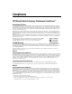
Appendix B Cabling Figure B-1 illustrates the Camera Link cable. 1 2 1 MDR 26-Pin Male Plug 2 2X Thumbscrews Figure B-1. Camera Link Cable Ordering Information Camera Link cables are manufactured by 3M corporation and are available from both National Instruments and 3M. Two-meter Camera Link cables (part number 187676-02) are available from the National Instruments Web site at ni.com/catalog. Camera Link cables are available in 1 to 10 m lengths from the 3M Web site at 3m.com.
Technical Support Resources C Web Support National Instruments Web support is your first stop for help in solving installation, configuration, and application problems and questions. Online problem-solving and diagnostic resources include frequently asked questions, knowledge bases, product-specific troubleshooting wizards, manuals, drivers, software updates, and more. Web support is available through the Technical Support section of ni.com. NI Developer Zone The NI Developer Zone at ni.
Appendix C Technical Support Resources Worldwide Support National Instruments has offices located around the world to help address your support needs. You can access our branch office Web sites from the Worldwide Offices section of ni.com. Branch office Web sites provide up-to-date contact information, support phone numbers, e-mail addresses, and current events.
Glossary Prefix Meaning Value k- kilo- 10 3 M- mega- 10 6 Numbers/Symbols % Percent. + Positive of, or plus. / Per. Ω Ohm. ± Plus or minus. – Negative of, or minus. A A Amperes. AC Alternating current. acquisition window The image size specific to a video standard or camera resolution. active line region The region of lines actively being stored. Defined by a line start (relative to the vertical synchronization signal) and a line count.
Glossary API Application programming interface. area A rectangular portion of an acquisition window or frame that is controlled and defined by software. array Ordered, indexed set of data elements of the same type. ASIC Application-Specific Integrated Circuit. A proprietary semiconductor component designed and manufactured to perform a set of specific functions for specific customer needs. B b Bit. One binary digit, either 0 or 1. B Byte.
Glossary D DAQ Data acquisition. (1) Collecting and measuring electrical signals from sensors, transducers, and test probes or fixtures and inputting them to a computer for processing. (2) Collecting and measuring the same kinds of electrical signals with A/D or DIO boards plugged into a computer, and possibly generating control signals with D/A and/or DIO boards in the same computer. DC Direct current.
Glossary F FIFO First-in first-out memory buffer. The first data stored is the first data sent to the acceptor; FIFOs are used on IMAQ devices to temporarily store incoming data until that data can be retrieved. ft Feet. H h Hour. Hz Hertz. Frequency in units of one cycle per second. I I/O Input/output. The transfer of data to/from a computer system involving communications channels, operator interface devices, and/or data acquisition and control interfaces. IC Integrated circuit.
Glossary K k Kilo. The standard metric prefix for 1,000, or 103, used with units of measure such as volts, hertz, and meters. K Kilo. The prefix for 1,024, or 210, used with B in quantifying data or computer memory. kbytes/s A unit for data transfer that means 1,000 or 103 bytes/s. Kword 1,024 words of memory. L line count The total number of horizontal lines in the picture. LSB Least significant bit. LUT Look-up table.
Glossary MSB Most significant bit. MTBF Mean time between failure. mux Multiplexer. A switching device with multiple inputs that selectively connects one of its inputs to its output. N NI-IMAQ Driver software for National Instruments IMAQ hardware. NVRAM Nonvolatile RAM. RAM that is not erased when a device loses power or is turned off.
Glossary R RAM Random-access memory. real time A property of an event or system in which data is processed as it is acquired instead of being accumulated and processed at a later time. relative accuracy A measure in LSB of the accuracy of an ADC; it includes all nonlinearity and quantization errors but does not include offset and gain errors of the circuitry feeding the ADC. resolution The smallest signal increment that can be detected by a measurement system.
Glossary SRAM Static RAM. sync Tells the display where to put a video picture. The horizontal sync indicates the picture’s left-to-right placement and the vertical sync indicates top-to-bottom placement. system RAM RAM installed on a personal computer and used by the operating system, as contrasted with onboard RAM. T tap A stream of pixels from a camera. Some cameras send multiple streams, or taps, of data over a cable simultaneously to increase transfer rate.
Index Numbers CC<4..1>± signal (table), 4-4 CHASSIS-GND signal (table), 4-3 clock signals XCLK±<1..0>± signal (table), 4-4 YCLK±<1..
Index H pattern-matching software for vision and motion, 1-7 relationship between programming environment, NI-IMAQ, and hardware (figure), 1-4 unpacking, 2-4 IMAQ Vision Builder software integration with DAQ, 1-7 overview, 1-6 to 1-7 pattern-matching capabilities, 1-7 installation cabling, B-1 to B-2 68-pin VHDCI cable specifications, B-1 Camera Link cables, B-1 to B-2 procedure, 2-6 to 2-7 safety information, 2-4 to 2-6 unpacking IMAQ PCI-1428, 2-4 I/O connector. See connectors.
Index O pattern-matching software for vision and motion, 1-7 relationship between programming environment, NI-IMAQ, and hardware (figure), 1-4 specifications clocks, A-1 environment, A-2 external connections, A-1 PCI interface, A-1 to A-2 physical, A-2 power requirements, A-2 start conditions delayed acquisition, 3-6 software control, 3-5 trigger control, 3-5 system integration, by National Instruments, C-1 optional equipment, 2-2 P PCI interface specifications, A-1 to A-2 physical specifications, A-2 p
Index W Y Web support from National Instruments, C-1 Worldwide technical support, C-2 Y<3..0>± signal (table), 4-4 YCLK±<1..0>± signal (table), 4-4 X X<3..0>± signal (table), 4-3 XCLK±<1..0>± signal (table), 4-4 IMAQ PCI-1428 User Manual I-4 ni.