IMAQ ™ IMAQ PCI/PXI™-1411 User Manual Single-Channel Color Image Acquisition Board for PCI, PXI, and CompactPCI Chassis IMAQ PCI/PXI-1411 User Manual October 1999 Edition Part Number 322157B-01
Worldwide Technical Support and Product Information www.ni.
Important Information Warranty The PCI-1411 and PXI-1411 are warranted against defects in materials and workmanship for a period of one year from the date of shipment, as evidenced by receipts or other documentation. National Instruments will, at its option, repair or replace equipment that proves to be defective during the warranty period. This warranty includes parts and labor.
Compliance FCC/Canada Radio Frequency Interference Compliance* Determining FCC Class The Federal Communications Commission (FCC) has rules to protect wireless communications from interference. The FCC places digital electronics into two classes. These classes are known as Class A (for use in industrialcommercial locations only) or Class B (for use in residential or commercial locations). Depending on where it is operated, this product could be subject to restrictions in the FCC rules.
interference to radio or television reception, which can be determined by turning the equipment off and on, the user is encouraged to try to correct the interference by one or more of the following measures: • Reorient or relocate the receiving antenna. • Increase the separation between the equipment and receiver. • Connect the equipment into an outlet on a circuit different from that to which the receiver is connected. • Consult the dealer or an experienced radio/TV technician for help.
Conventions The following conventions are used in this manual: ♦ The ♦ symbol indicates that the following text applies only to a specific product, a specific operating system, or a specific software version. This icon denotes a note, which alerts you to important information. This icon denotes a warning, which advises you of precautions to take to avoid being electrically shocked. italic Italic text denotes variables, emphasis, a cross reference, or an introduction to a key concept.
Contents Chapter 1 Introduction About the PCI/PXI-1411 .................................................................................................1-1 Using PXI with CompactPCI...........................................................................................1-2 Software Programming Choices ......................................................................................1-2 NI-IMAQ Driver Software ................................................................................
Contents Chapter 4 Signal Connections I/O Connector .................................................................................................................. 4-1 Signal Description ........................................................................................................... 4-2 Custom Cables.................................................................................................................
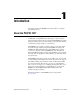
1 Introduction This chapter describes the PCI/PXI-1411 and describes your software programming choices. About the PCI/PXI-1411 The PCI/PXI-1411 is a highly flexible monochrome and color IMAQ board for PCI, PXI, or CompactPCI chassis that supports a diverse range of analog cameras from many camera companies. The PCI/PXI-1411 acquires images in real time and can store these images in onboard frame memory, or transfer these images directly to system memory.
Chapter 1 Introduction Using PXI with CompactPCI Using PXI-compatible products with standard CompactPCI products is an important feature provided by the PXI Specification, Revision 1.0. If you use a PXI-compatible plug-in device in a standard CompactPCI chassis, you will be unable to use PXI-specific functions, but you can still use the basic plug-in device functions. The CompactPCI specification permits vendors to develop sub-buses that coexist with the basic PCI interface on the CompactPCI bus.
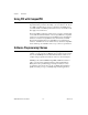
Chapter 1 Introduction Vision Software IMAQ Vision Image Analysis Blob Analysis Pattern Matching Color Matching and Analysis Filters Gauging and Measurement Display and ROI Morphology Application Software BridgeVIEW ActiveX LabWindows/CVI (ComponentWorks) LabVIEW NI-IMAQ IMAQ Driver Software NI-DAQ Hardware DAQ ValueMotion/ FlexMotion ValueMotion/ FlexMotion Figure 1-1.
Chapter 1 Introduction NI-IMAQ Image Acquisition Triggering and Timing DAQ Synchronization Buffer Control Camera Control Look-up Table Control Figure 1-2. NI-IMAQ Functions The NI-IMAQ driver software performs all functions required for acquiring and saving images. The NI-IMAQ software does not perform any image analysis. For image analysis functionality, refer to the National Instruments IMAQ Vision section in this chapter.
Chapter 1 Introduction National Instruments IMAQ Vision IMAQ Vision is an image acquisition, processing, and analysis library of more than 200 functions for grayscale, color, and binary image display, image processing, pattern matching, shape matching, blob analysis, gauging, and measurement. You can use IMAQ Vision functions directly or in combination for unique image processing.
Chapter 1 Introduction Integration with DAQ Any platform that supports NI-IMAQ also supports NI-DAQ and a variety of National Instruments DAQ boards, so your IMAQ device and NI-IMAQ development can integrate with National Instruments DAQ products. Vision and Motion With National Instruments IMAQ hardware and IMAQ Vision pattern matching software you can quickly and accurately locate objects in instances where objects vary in size, orientation, focus, and even when the part is poorly illuminated.
2 Installation This chapter lists what you need to get started acquiring images with your IMAQ device; describes optional equipment and custom cables; and explains how to unpack, configure, and install your IMAQ device.
Chapter 2 Installation Optional Equipment National Instruments offers a variety of products for use with your PCI/PXI-1411, including other National Instruments DAQ devices for enhanced triggering, timing, or input/output. For more specific information about these products, refer to your National Instruments catalogue or Web site, or call the office nearest you.
Chapter 2 Installation Read the Getting Started with Your IMAQ System document and the NI-IMAQ release notes to install your NI-IMAQ software, IMAQ hardware, and documentation. Configure your hardware using the Measurement & Automation Explorer and online help. LabWindows/CVI Third-Party Compilers What application software are you using? LabVIEW BridgeVIEW ComponentWorks Read Chapter 1, Introduction to NI-IMAQ, in the NI-IMAQ User Manual.
Chapter 2 Installation Unpacking Your PCI/PXI-1411 is shipped in an antistatic package to prevent electrostatic damage to the board. Electrostatic discharge can damage several components on the board. To avoid such damage in handling the board, take the following precautions: • Ground yourself via a grounding strap or by holding a grounded object. • Touch the antistatic package to a metal part of your computer chassis before removing the board from the package.
Chapter 2 Installation 4. Locate the metal bracket that covers the cut-out in the back panel of the chassis for the slot you have selected. Remove and save the bracket-retaining screw and the bracket cover. 5. Touch the metal part of the power supply case inside the computer to discharge any static electricity that might be on your clothes or body. 6. Line up the PCI-1411 with the BNC connectors near the cut-out on the back panel.
3 Hardware Overview This chapter presents an overview of the hardware functions on your PCI/PXI-1411 board and explains the operation of each functional unit making up the PCI/PXI-1411. Functional Overview The PCI/PXI-1411 features a flexible, high-speed data path optimized for the acquisition and formatting of video data from analog monochrome and color cameras.
Chapter 3 Hardware Overview Video Decoder The PCI/PXI-1411 supports NTSC and PAL video standards in either composite or S-Video format. The onboard video decoder converts the incoming video signal to Red, Green, and Blue (RGB) data and passes this data to the color-space processor for further processing. The video decoder also allows you to control numerous parameters to optimize an acquisition.
Chapter 3 Hardware Overview SDRAM The PCI/PXI-1411 comes with 16 MB of onboard high-speed synchronous dynamic RAM (SDRAM). The PCI/PXI-1411 can use the onboard RAM as a first-in first-out (FIFO) buffer, transferring the image data as it is acquired or acquiring the image data into SDRAM and holding it for later transfer to main memory. Trigger Control and Mapping Circuitry The trigger control monitors and drives the external trigger line.
Chapter 3 Hardware Overview Bus Master PCI Interface The PCI/PXI-1411 implements the PCI interface with a National Instruments custom application-specific integrated circuit (ASIC), the PCI MITE. The PCI interface can transfer data at a maximum rate of 132 Mbytes/s in bus master mode. The PCI/PXI-1411 can generate 8-, 16-, and 32-bit memory read and write cycles, both single and multiple. In slave mode, the PCI/PXI-1411 is a medium-speed decoder that accepts both memory and configuration cycles.
Chapter 3 Hardware Overview • Region of interest—The PCI/PXI-1411 uses a second level of active pixel and active line regions for selecting a region of interest. When you disable the region-of-interest circuitry, the board stores the entire acquisition window into with onboard or system memory. However, when you enable the region-of-interest circuitry, the board acquires only a selected subset of the image frame. • Scaling down—The scaling down circuitry also controls the active acquisition region.
4 Signal Connections This chapter describes cable connections for the PCI/PXI-1411. I/O Connector The PCI/PXI-1411 uses one S-Video and two BNC connectors on the front panel to connect to video data inputs and the external trigger signal. Figure 4-1 shows the position of the three connectors. VIDEO S-VIDEO TRIG Figure 4-1.
Chapter 4 Signal Connections Signal Description Table 4-1 describes each signal connection on the 1411 device connectors: Table 4-1. I/O Connector Signals Signal Name Description VIDEO Composite Video—The signal allows you to make a referenced single-ended (RSE) connection to the video channel. S-VIDEO S-Video—A connector composed of two signals, as follows: Y—The Y signal of the S-Video connection contains the luma and synchronization information of the video signal.
A Specifications This appendix lists the specifications of the PCI/PXI-1411. These specifications are typical at 25 °C, unless otherwise stated. Formats Supported Input formats RS-170/NTSC ................................. 29.97 frames/s CCIR/PAL ...................................... 25 frames/s Output formats RGB ............................................... 32-bit HSL ................................................. 32-bit R, G, B, H, S, or L .......................... 8-bit Pixel aspect ratio ....
Appendix A Specifications A/D Conversion Quantity ..................................................One 8-bit 2X oversampling for composite video Two 8-bit 2X oversampling for Y/C (S-Video) Dynamic range........................................46 dB typ Sampling Frequency RS-170/NTSC..................................27.54 MHz (double rate of square pixel CCIR/PAL .......................................29.5 MHz (double rate of square pixel) Color Decoding Composite video Luma path..........................
Appendix A Specifications PCI Interface PCI initiator (master) capability............. Supported PCI target (slave) capability................... Supported Data path ................................................ 32 bits Board voltage ......................................... 5 V, 12 V, –12 V Board type .............................................. 32-bit half-size card Parity generation/checking, error reporting ........................................ Supported Target decode speed....................
Appendix A Specifications Physical Dimensions PCI-1411..........................................10.7 by 17.5 cm (4.2 by 6.9 in.) PXI-1411 .........................................10 by 16 cm (3.9 by 6.3 in.) Weight PCI-1411..........................................0.136 kg (0.3 lb.) PXI-1411 .........................................0.154 kg (0.34 lb.) Environment Operating temperature ............................ 0–55 °C Storage temperature ................................–20–70 °C Relative humidity ....
B Introduction to Color Color is the wavelength of the light we receive in our eye when we look at an object. In theory, the color spectrum is infinite. Humans, however, can see only a small portion of this spectrum—the portion that goes from the red edge of infrared light (the longest wavelength) to the blue edge of ultraviolet light (the shortest wavelength). This continuous spectrum is called the visible spectrum, as shown in Figure B-1. Figure B-1.
Appendix B Introduction to Color The perception of a color depends on many factors, such as: • Hue, which is the perceived dominant color. Hue depends directly on the wavelength of a color. • Saturation, which is dependent on the amount of white light present in a color. Pastels typically have a low saturation while very rich colors have a high saturation. For example, pink typically has a red hue but has a low saturation. • Luminance, which is the brightness information in the video picture.
Appendix B Introduction to Color Hue, Saturation, Luminance, and Intensity Planes The 8-bit hue, saturation, luminance, and intensity planes can also be returned individually if you want to analyze the image. Luminance, Intensity, Hue, or Saturation are defined using the Red, Green, and Blue values in the following formulas: Luminance = 0.299 × Red + 0.587 × Green + 0.
Technical Support Resources C This appendix describes the comprehensive resources available to you in the Technical Support section of the National Instruments Web site and provides technical support telephone numbers for you to use if you have trouble connecting to our Web site or if you do not have internet access. NI Web Support To provide you with immediate answers and solutions 24 hours a day, 365 days a year, National Instruments maintains extensive online technical support resources.
Appendix C Technical Support Resources Software-Related Resources • Instrument Driver Network—A library with hundreds of instrument drivers for control of standalone instruments via GPIB, VXI, or serial interfaces. You also can submit a request for a particular instrument driver if it does not already appear in the library. • Example Programs Database—A database with numerous, non-shipping example programs for National Instruments programming environments.
Glossary Prefix Meaning Value p- pico- 10 –12 n- nano- 10 –9 µ- micro- 10 – 6 m- milli- 10 –3 k- kilo- 10 3 M- mega- 10 6 G- giga- 10 9 t- tera- 10 12 Numbers/Symbols + Positive of, or plus. / Per. Ω Ohm. ± Plus or minus. – Negative of, or minus. A A Amperes. AC Alternating current. acquisition window The image size specific to a video standard or camera resolution. active line region The region of lines actively being stored.
Glossary active pixel region The region of pixels actively being stored. Defined by a pixel start (relative to the horizontal synchronization signal) and a pixel count. address Value that identifies a specific location (or series of locations) in memory. API Application programming interface. area A rectangular portion of an acquisition window or frame that is controlled and defined by software. array Ordered, indexed set of data elements of the same type.
Glossary color space The mathematical representation for a color. For example, color can be described in terms of red, green, and blue; hue, saturation, and luma; or hue, saturation, and intensity. composite video A type of color video transmission where synchronization, luma, and chroma information are transmitted on one analog signal. contrast A constant multiplication factor applied to the luma and chroma components of a color pixel in the color decoding process.
Glossary drivers Software that controls a specific hardware device, such as an image acquisition board. dynamic range The ratio of the largest signal level a circuit can handle to the smallest signal level it can handle (usually taken to be the noise level), normally expressed in decibels. E EEPROM Electrically erasable programmable read-only memory. ROM that can be erased with an electrical signal and reprogrammed.
Glossary H h Hour. HSI Color encoding scheme in Hue, Saturation, and Intensity. HSL Color encoding scheme using Hue, Saturation, and Luma information where each image in the pixel is encoded using 32 bits: 8 bits for hue, 8 bits for saturation, 8 bits for luma, and 8 unused bits. HSYNC Horizontal synchronization signal. The synchronization pulse signal produced at the beginning of each video scan line that keeps a video monitor’s horizontal scan rate in step with the transmission of each new line.
Glossary intensity The sum of the Red, Green, and Blue primaries divided by three: (Red + Green + Blue)/3. interlaced A video frame composed of two interleaved fields. The number of lines in a field are half the number of lines in an interlaced frame. interrupt A computer signal indicating that the CPU should suspend its current task to service a designated activity. interrupt level The relative priority at which a device can interrupt. IRQ Interrupt request. See interrupt. K k Kilo.
Glossary M m Meters. M (1) Mega, the standard metric prefix for 1 million or 106, when used with units of measure such as volts and hertz; (2) mega, the prefix for 1,048,576, or 220, when used with B to quantify data or computer memory. MB Megabyte of memory. Mbytes/s A unit for data transfer that means 1 million or 106 bytes/s. memory buffer See buffer. memory window Continuous blocks of memory that can be accessed quickly by changing addresses on the local processor.
Glossary P PAL Phase Alternation Line. One of the European video color standards; uses 625 lines per frame. See also NTSC. PCI Peripheral Component Interconnect. A high-performance expansion bus architecture originally developed by Intel to replace ISA and EISA. PCI offers a theoretical maximum transfer rate of 132 Mbytes/s. pixel Picture element.
Glossary RGB Color encoding scheme using red, green, and blue (RGB) color information where each pixel in the color image is encoded using 32 bits: 8 bits for red, 8 bits for green, 8 bits for blue, and 8 bits for the alpha value (unused). ROI Region of interest. A hardware-programmable rectangular portion of the acquisition window. ROM Read-only memory. RS-170 The U.S. standard used for black-and-white television. RSE Referenced single-ended.
Glossary T transfer rate The rate, measured in bytes/s, at which data is moved from source to destination after software initialization and set up operations. The maximum rate at which the hardware can operate. trigger Any event that causes or starts some form of data capture. trigger control and mapping circuitry Circuitry that routes, monitors, and drives external and RTSI bus trigger lines. You can configure each of these lines to start or stop acquisition on a rising or falling edge.
Index A connector for PCI/PXI-1411 (figure), 4-1 custom cables, 4-2 accuracy specifications, A-2 acquisition acquisition, scaling, and ROI circuitry, 3-3 acquisition window control, 3-4 to 3-5 start conditions, 3-4 acquisition window, 3-4 A/D conversion specifications, A-2 D diagnostic resources, online, C-1 DMA controllers, scatter-gather, 3-3 E environment specifications, A-4 equipment, optional, 2-2 external connection specifications, A-2 B block diagram of PCI/PXI-1411, 3-1 board configuration NVRA
Index M video acquisition, 3-1 video decoder, 3-2 mapping circuitry and trigger control, 3-3 memory board configuration NVRAM, 3-4 SDRAM, 3-3 specifications, A-2 hue 32-bit HSL and HSI, B-3 definition, B-2 hue, saturation, luminance, and intensity planes, B-3 N I National Instruments Web support, C-1 to C-2 NI-IMAQ driver software, 1-3 to 1-4 NTSC video standard, 3-2 NVRAM, 3-4 image representations, B-2 to B-3 32-bit HSL and HSI, B-3 color planes, B-2 hue, saturation, luminance, and intensity plane
Index R external connections, A-2 formats supported, A-1 memory, A-2 PCI interface, A-3 physical, A-4 power requirements, A-3 video input, A-1 start conditions, 3-4 S-VIDEO signal (table), 4-2 RAM board configuration NVRAM, 3-4 SDRAM, 3-3 region of interest acquisition, scaling, and ROI circuitry, 3-3 configuring, 3-5 requirements for getting started, 2-1 RGB image representation, B-2 T S technical support resources, C-1 to C-2 TRIG signal (table), 4-2 trigger control and mapping circuitry, 3-3 satura