NI Vision NI PCI-1405 User Manual Single-Channel Color Image Acquisition Device NI PCI-1405 User Manual February 2007 373687B-01
Support Worldwide Technical Support and Product Information ni.
Important Information Warranty The NI PCI-1405 is warranted against defects in materials and workmanship for a period of one year from the date of shipment, as evidenced by receipts or other documentation. National Instruments will, at its option, repair or replace equipment that proves to be defective during the warranty period. This warranty includes parts and labor.
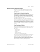
Compliance Compliance with FCC/Canada Radio Frequency Interference Regulations Determining FCC Class The Federal Communications Commission (FCC) has rules to protect wireless communications from interference. The FCC places digital electronics into two classes. These classes are known as Class A (for use in industrial-commercial locations only) or Class B (for use in residential or commercial locations). All National Instruments (NI) products are FCC Class A products.
Conventions The following conventions are used in this manual: » The » symbol leads you through nested menu items and dialog box options to a final action. The sequence File»Page Setup»Options directs you to pull down the File menu, select the Page Setup item, and select Options from the last dialog box. This icon denotes a note, which alerts you to important information. This icon denotes a caution, which advises you of precautions to take to avoid injury, data loss, or a system crash.
Contents Chapter 1 Introduction About the NI 1405 .........................................................................................................1-1 Software Overview ........................................................................................................1-2 NI-IMAQ Driver Software ..............................................................................1-2 National Instruments Application Software ....................................................
Contents Glossary Index NI PCI-1405 User Manual viii ni.
1 Introduction This chapter describes the NI PCI-1405 (NI 1405) and the software programming choices. About the NI 1405 The NI 1405 is a PCI monochrome and color image acquisition device that supports a diverse range of analog cameras from many camera companies. The NI 1405 acquires images in real time and can store these images in onboard frame memory or transfer these images directly to system memory. The NI 1405 is easy to configure, which allows you to begin acquiring images quickly.
Chapter 1 Introduction Software Overview Programming the NI 1405 requires the NI-IMAQ driver software for controlling the hardware. National Instruments also offers the following application software packages for analyzing and processing your acquired images: • Vision Builder for Automated Inspection (AI)—Allows you to configure solutions for common inspection tasks. • Vision Development Module—Provides customized control over hardware and algorithms.
Chapter 1 Introduction National Instruments Application Software This section describes the National Instruments application software packages you can use to analyze and process the images you acquire with the NI 1405. Vision Builder for Automated Inspection NI Vision Builder for Automated Inspection (AI) is configurable machine vision software that you can use to prototype, benchmark, and deploy applications for use in LabVIEW, LabWindows/CVI, and Measurement Studio.
Chapter 1 Introduction NI Vision Assistant is included with the Vision Development Module. Vision Assistant is an interactive prototyping tool for machine vision and scientific imaging developers. With Vision Assistant, you can prototype vision applications quickly and test how various vision image processing functions work. Vision Assistant generates a Builder file, which is a text description containing a recipe of the machine vision and image processing functions.
2 Hardware Overview This chapter presents an overview of the hardware functions on the NI 1405 and explains the operation of each functional unit making up the NI 1405. Functional Overview The NI 1405 features a high-speed data path optimized for the acquisition and formatting of video data from analog monochrome and color cameras. The block diagram in Figure 2-1 illustrates the key functional components of the NI 1405.
Chapter 2 Hardware Overview Video Acquisition The NI 1405 can acquire analog color video in a variety of modes and then store the images in the onboard SDRAM memory or transfer the images directly to PCI system memory. Video Decoder The NI 1405 supports NTSC and PAL video standards in composite format. The onboard video decoder converts the incoming video signal to red, green, and blue (RGB) data. The video decoder allows you to control numerous parameters to optimize an acquisition.
Chapter 2 Hardware Overview Acquisition and ROI Circuitry The acquisition and region-of-interest (ROI) circuitry monitors the incoming video signals and routes the active pixels to the SDRAM memory. The NI 1405 can perform an ROI acquisition on all video lines and frames. In an ROI acquisition, you select an area within the acquisition window to transfer to the PCI bus. Scatter-Gather DMA Controllers The NI 1405 uses three independent onboard direct memory access (DMA) controllers.
Chapter 2 Hardware Overview Acquisition Window Control You can configure numerous parameters on the NI 1405 to control the video acquisition window. A brief description of each parameter follows: NI PCI-1405 User Manual • Acquisition window—The NI 1405 allows you to specify a particular region of active pixels and active lines within the incoming video data.
3 Signal Connections This chapter describes cable connections for the NI 1405. Connectors The NI 1405 uses two BNC connectors on the front panel to connect to video data input and the external trigger signal. Figure 3-1 shows the position of the connectors. VIDEO TRIG Figure 3-1.
Chapter 3 Signal Connections Signal Descriptions Table 3-1 describes the signal connections on the NI 1405 connectors. Table 3-1. I/O Connector Signals Signal Name Description VIDEO Composite Video—This signal allows you to make a referenced single-ended (RSE) connection to the video channel. TRIG External trigger—You can use this TTL I/O line to start an acquisition or to control external events. You can program the triggers to be risingor falling-edge sensitive.
A Introduction to Color Color is the wavelength of the light we receive in our eye when we look at an object. In theory, the color spectrum is infinite. Humans, however, can see only a small portion of this spectrum—the portion that goes from the red edge of infrared light, which is the longest wavelength, to the blue edge of ultraviolet light, which is the shortest wavelength. This continuous spectrum is called the visible spectrum, as shown in Figure A-1. Figure A-1.
Appendix A Introduction to Color The perception of a color depends on many factors, such as the following: • Hue, which is the perceived dominant color. Hue depends directly on the wavelength of a color. • Saturation, which is dependent on the amount of white light present in a color. Pastels typically have a low saturation while very rich colors have a high saturation. For example, pink typically has a red hue but has a low saturation.
Appendix A Introduction to Color Hue, Saturation, Luminance, and Intensity Planes The NI 1405 can return an 8-bit Luminance (L) plane, but not Hue (H) or Saturation (S) planes. You can use the NI Vision Development Module or Vision Builder AI to convert the RGB data from the NI 1405 to HSL or Hue, Saturation, and Intensity (HSI) planes. Luminance, intensity, hue, and saturation are defined using the red, green, and blue values in the following formulas: Luminance = 0.299 × Red + 0.587 × Green + 0.
Technical Support and Professional Services B Visit the following sections of the National Instruments Web site at ni.com for technical support and professional services: • Support—Online technical support resources at ni.
Appendix B Technical Support and Professional Services • Declaration of Conformity (DoC)—A DoC is our claim of compliance with the Council of the European Communities using the manufacturer’s declaration of conformity. This system affords the user protection for electronic compatibility (EMC) and product safety. You can obtain the DoC for your product by visiting ni.com/certification.
Glossary A acquisition window The image size specific to a video standard or camera resolution. active line region The region of lines actively being stored. Defined by a line start (relative to the vertical synchronization signal) and a line count. active pixel region The region of pixels actively being stored. Defined by a pixel start (relative to the horizontal synchronization signal) and a pixel count. address Value that identifies a specific location (or series of locations) in memory.
Glossary composite video A type of color video transmission where synchronization, luma, and chroma information are transmitted on one analog signal. contrast A constant multiplication factor applied to the luma and chroma components of a color pixel in the color decoding process. D DAQ Data acquisition. (1) Collecting and measuring electrical signals from sensors, transducers, and test probes or fixtures and inputting them to a computer for processing.
Glossary F field For an interlaced video signal, a field is half the number of horizontal lines needed to represent a frame of video. The first field of a frame contains all the odd-numbered lines, the second field contains all of the even-numbered lines. FIFO First-in first-out memory buffer. The first data stored is the first data sent to the acceptor; FIFOs are used on devices to temporarily store incoming data until that data can be retrieved. frame A complete image.
Glossary interlaced A video frame composed of two interleaved fields. The number of lines in a field are half the number of lines in an interlaced frame. interrupt A computer signal indicating that the CPU should suspend its current task to service a designated activity. L luma The brightness information in the video picture. The luma signal amplitude varies in proportion to the brightness of the video signal and corresponds exactly to the monochrome picture. M MTBF Mean time between failure.
Glossary pixel count The total number of pixels between two horizontal synchronization signals. The pixel count determines the frequency of the pixel clock. R real time A property of an event or system in which data is processed as it is acquired instead of being accumulated and processed at a later time. resolution The smallest signal increment that can be detected by a measurement system. Resolution can be expressed in bits, in proportions, or in percent of full scale.
Glossary trigger control and mapping circuitry Circuitry that routes, monitors, and drives the external trigger line. You can configure this line to start or stop acquisition on a rising or falling edge. TTL Transistor-transistor logic. V VI NI PCI-1405 User Manual Virtual Instrument.
Index A documentation conventions used in the manual, v NI resources, B-1 drivers (NI resources), B-1 acquisition acquisition and ROI circuitry, 2-3 acquisition window control, 2-4 start conditions, 2-3 acquisition window, 2-4 E examples (NI resources), B-1 B block diagram of NI 1405, 2-1 bus master PCI interface, 2-3 F functional overview, 2-1 C H calibration certificate (NI resources), B-2 color overview definition of color, A-1 image representations 32-bit HSL and HSI, A-3 color planes, A-2 hue,
Index I NI support and services, B-1 NTSC video standard, 2-2 I/O connector (figure), 3-1 image representations 32-bit HSL and HSI, A-2 color planes, A-2 hue, saturation, luminance, and intensity planes, A-3 RGB, A-2 instrument drivers (NI resources), B-1 integration with DAQ and motion control, 1-4 intensity 32-bit HSL and HSI, A-3 definition, A-2 hue, saturation, luminance, and intensity planes, A-3 P PAL video standard, 2-2 post-decoding coring, 2-2 programming examples (NI resources), B-1 R RAM, SD
Index T W technical support, B-1 training and certification (NI resources), B-1 TRIG signal (table), 3-2 trigger control and mapping circuitry, 2-2 troubleshooting (NI resources), B-1 Web resources, B-1 V video acquisition, 2-2 video decoder, 2-2 VIDEO signal (table), 3-2 video standards, 2-2 © National Instruments Corporation I-3 NI PCI-1405 User Manual