
Network Card User Manual
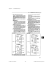
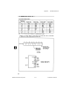
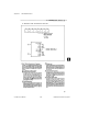
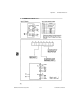
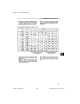
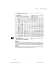
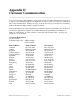
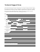
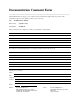
Table Of Contents
- PC-DIO-24 User Manual
- Contents
- About This Manual
- Chapter 1 Introduction
- Chapter 2 Configuration and Installation
- Chapter 3 Theory of Operation
- Chapter 4 Register-Level Programming
- Appendix A Specifications
- Appendix B I/O Connector
- Appendix C OKI 82C55A Data Sheet*
- Appendix D Customer Communication
- Glossary
- Index
- Figures
- Figure 1-1. The Relationship between the Programming Environment, NI-DAQ, and Your Hardware
- Figure 2-1. PC-DIO-24 Parts Locator Diagram
- Figure 2-2. Example Base I/O Address Switch Settings
- Figure 2-3. Jumper Settings–PC6, PC4, PC2, and N/C
- Figure 2-4. Interrupt Jumper Setting for IRQ5 (Factory Setting)
- Figure 2-5. Digital I/O Connector Pin Assignments
- Figure 3-1. PC-DIO-24 Block Diagram
- Figure 4-1. Control-Word Formats
- Figure B-1. PC-DIO-24 I/O Connector
- Tables
- Table 2-1. PC-DIO-24 Factory-Set Jumper and Switch Settings
- Table 2-2. Port C Signal Assignments
- Table 4-1. PC-DIO-24 Address Map
- Table 4-2. Port C Set/Reset Control Words
- Table 4-3. Mode 0 I/O Configurations
- Table 4-4. Interrupt Enable Signals for All Mode Combinations
- Table A-1. Maximum Average Transfer Rates for the PC-DIO-24
PC-DIO-24 Hardware and Software
Configuration Form
___________________________________________________
Record the settings and revisions of your hardware and software on the line to the right of each item. Complete a
new copy of this form each time you revise your software or hardware configuration, and use this form as a
reference for your current configuration. Completing this form accurately before contacting National Instruments
for technical support helps our applications engineers answer your questions more efficiently.
National Instruments Products
• PC-DIO-24 Revision _________________________________________________
• Base I/O Address of PC-DIO-24
(Factory Setting–hex 210) _________________________________________________
• Interrupt Enable Line of PC-DIO-24
(Factory Setting–PC4) _________________________________________________
• Interrupt Level of PC-DIO-24
(Factory Setting–5) _________________________________________________
• Handshaking Mode
(mode 0, mode 1, mode 2) _________________________________________________
• NI-DAQ or LabWindows/CVI Version _________________________________________________
Other Products
• Computer Make and Model _________________________________________________
• Microprocessor _________________________________________________
• Clock Frequency _________________________________________________
• Type of Video Board Installed _________________________________________________
• DOS Version _________________________________________________
• Programming Language _________________________________________________
• Programming Language Version _________________________________________________
• Other Boards in System _________________________________________________
• Base I/O Address of Other Boards _________________________________________________
• Interrupt Enable Line
of Other Boards _________________________________________________
• Interrupt Level of Other Boards _________________________________________________