
Network Card User Manual
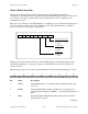
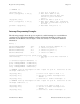
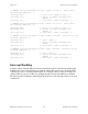
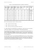

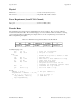
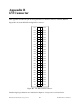
Table Of Contents
- PC-DIO-24 User Manual
- Contents
- About This Manual
- Chapter 1 Introduction
- Chapter 2 Configuration and Installation
- Chapter 3 Theory of Operation
- Chapter 4 Register-Level Programming
- Appendix A Specifications
- Appendix B I/O Connector
- Appendix C OKI 82C55A Data Sheet*
- Appendix D Customer Communication
- Glossary
- Index
- Figures
- Figure 1-1. The Relationship between the Programming Environment, NI-DAQ, and Your Hardware
- Figure 2-1. PC-DIO-24 Parts Locator Diagram
- Figure 2-2. Example Base I/O Address Switch Settings
- Figure 2-3. Jumper Settings–PC6, PC4, PC2, and N/C
- Figure 2-4. Interrupt Jumper Setting for IRQ5 (Factory Setting)
- Figure 2-5. Digital I/O Connector Pin Assignments
- Figure 3-1. PC-DIO-24 Block Diagram
- Figure 4-1. Control-Word Formats
- Figure B-1. PC-DIO-24 I/O Connector
- Tables
- Table 2-1. PC-DIO-24 Factory-Set Jumper and Switch Settings
- Table 2-2. Port C Signal Assignments
- Table 4-1. PC-DIO-24 Address Map
- Table 4-2. Port C Set/Reset Control Words
- Table 4-3. Mode 0 I/O Configurations
- Table 4-4. Interrupt Enable Signals for All Mode Combinations
- Table A-1. Maximum Average Transfer Rates for the PC-DIO-24

Specifications Appendix A
PC-DIO-24 User Manual A-2 © National Instruments Corporation
Physical
Dimensions.................................................................. 17.5 by 9.9 cm (6.9 in. by 3.9 in.)
I/O connector............................................................... 50-pin male ribbon-cable connector
Power Requirement (from PC I/O Channel)
Typ power ................................................................... 0.10 A at 5 VDC (±10%)
Max power .................................................................. 0.16 A at 5 VDC (±10%)
Transfer Rates
The maximum average transfer rates for the PC-DIO-24 are shown as follows. The code used to make the
measurements follows the table. The assembly language code was assembled as inline assembly C code using
version 8.00 of the Microsoft Optimizing C Compiler. The C code was compiled using version 8.00 of the
Microsoft Optimizing C Compiler.
Table A-1. Maximum Average Transfer Rates for the PC-DIO-24
Bus CPU CPU Speed Assembly C
AT (ISA16) 486DX4 100 MHz 410 kbytes/s 330 kbytes/s
Assembly language code:
mov cx, 64 ; Count out 64 transfers
mov dx, 0180h ; The port to access
loop:
lodsb ; Assume ds:si points to buffer of data
out dx, al ; Send the data
add dx, 0014h ; Add offset to base address for Ireg1
in al, dx ; Dummy read from Ireg1
sub dx, 0014h ; Restore base address
; The previous four lines are not
; necessary for measuring transfer rates
dec cx ; Decrement the loop counter
jnz short loop ; See if we need to loop
C code:
address = 0x0180; /* The port address */
ireg1address = address + 0x0014;
for (i = 0; i < 64; i++) { /* Loop 64 times */
outp(address, *data++); /* Send data */
inp(ireg1address);
}