
Network Card User Manual
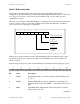
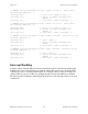

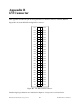
Table Of Contents
- PC-DIO-24 User Manual
- Contents
- About This Manual
- Chapter 1 Introduction
- Chapter 2 Configuration and Installation
- Chapter 3 Theory of Operation
- Chapter 4 Register-Level Programming
- Appendix A Specifications
- Appendix B I/O Connector
- Appendix C OKI 82C55A Data Sheet*
- Appendix D Customer Communication
- Glossary
- Index
- Figures
- Figure 1-1. The Relationship between the Programming Environment, NI-DAQ, and Your Hardware
- Figure 2-1. PC-DIO-24 Parts Locator Diagram
- Figure 2-2. Example Base I/O Address Switch Settings
- Figure 2-3. Jumper Settings–PC6, PC4, PC2, and N/C
- Figure 2-4. Interrupt Jumper Setting for IRQ5 (Factory Setting)
- Figure 2-5. Digital I/O Connector Pin Assignments
- Figure 3-1. PC-DIO-24 Block Diagram
- Figure 4-1. Control-Word Formats
- Figure B-1. PC-DIO-24 I/O Connector
- Tables
- Table 2-1. PC-DIO-24 Factory-Set Jumper and Switch Settings
- Table 2-2. Port C Signal Assignments
- Table 4-1. PC-DIO-24 Address Map
- Table 4-2. Port C Set/Reset Control Words
- Table 4-3. Mode 0 I/O Configurations
- Table 4-4. Interrupt Enable Signals for All Mode Combinations
- Table A-1. Maximum Average Transfer Rates for the PC-DIO-24
Register-Level Programming Chapter 4
PC-DIO-24 User Manual 4-14 © National Instruments Corporation
/* EXAMPLE 1*/
outp(cnfg,0xC0); /* Port A is in mode 2. */
while (!(inp(portc) & 0x80)); /* Wait until OBFA* is set,
indicating that the data last
written to port A has been
read.*/
outp(porta,0x67); /* Write the data to port A. */
while (!(inp(portc) & 0x20)); /* Wait until IBFA is set, indicating
that data is available in port A to
be read. */
valread = inp(porta); /* Read data from port A. */
}
Interrupt Programming Examples
The following examples show the process required to enable interrupts for several different
operating modes. The interrupt handling routines and interrupt installation routines are not
included. See the IBM Personal Computer AT Technical Reference manual for additional
information.
Main() {
#define BASE_ADDRESS 0x210 /* Board located at address 210. */
#define PORTAoffset 0x00 /* Offset for port A */
#define PORTBoffset 0x01 /* Offset for port B */
#define PORTCoffset 0x02 /* Offset for port C */
#define CNFGoffset 0x03 /* Offset for CNFG */
register unsigned int porta, portb, portc, cnfg;
char valread; /* Variable to store data read from a
port */
/* Calculate register addresses. */
porta = BASE_ADDRESS + PORTAoffset;
portb = BASE_ADDRESS + PORTBoffset;
portc = BASE_ADDRESS + PORTCoffset;
cnfg = BASE_ADDRESS + CNFGoffset;
/* EXAMPLE 1–Set up interrupts for mode 1 input for port A. Select PC6 as the
interrupt enable bit. */
outp(cnfg,0xB0); /* Port A is an input in mode 1. */
outp(cnfg,0x09); /* Set PC4 to enable interrupts from
82C55A. */
outp(cnfg,0x0C); /* Clear PC6 to enable interrupts. */
/* EXAMPLE 2–Set up interrupts for mode 1 input for port B. Select PC6 as the
interrupt enable bit. */
outp(cnfg,0x86); /* Port B is an input in mode 1. */
outp(cnfg,0x05); /* Set PC2 to enable interrupts from
82C55A. */
outp(cnfg,0x0C); /* Clear PC6 to enable interrupts. */