
Network Card User Manual
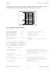
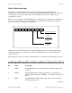
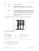
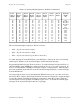

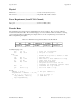
Table Of Contents
- PC-DIO-24 User Manual
- Contents
- About This Manual
- Chapter 1 Introduction
- Chapter 2 Configuration and Installation
- Chapter 3 Theory of Operation
- Chapter 4 Register-Level Programming
- Appendix A Specifications
- Appendix B I/O Connector
- Appendix C OKI 82C55A Data Sheet*
- Appendix D Customer Communication
- Glossary
- Index
- Figures
- Figure 1-1. The Relationship between the Programming Environment, NI-DAQ, and Your Hardware
- Figure 2-1. PC-DIO-24 Parts Locator Diagram
- Figure 2-2. Example Base I/O Address Switch Settings
- Figure 2-3. Jumper Settings–PC6, PC4, PC2, and N/C
- Figure 2-4. Interrupt Jumper Setting for IRQ5 (Factory Setting)
- Figure 2-5. Digital I/O Connector Pin Assignments
- Figure 3-1. PC-DIO-24 Block Diagram
- Figure 4-1. Control-Word Formats
- Figure B-1. PC-DIO-24 I/O Connector
- Tables
- Table 2-1. PC-DIO-24 Factory-Set Jumper and Switch Settings
- Table 2-2. Port C Signal Assignments
- Table 4-1. PC-DIO-24 Address Map
- Table 4-2. Port C Set/Reset Control Words
- Table 4-3. Mode 0 I/O Configurations
- Table 4-4. Interrupt Enable Signals for All Mode Combinations
- Table A-1. Maximum Average Transfer Rates for the PC-DIO-24

Register-Level Programming Chapter 4
PC-DIO-24 User Manual 4-12 © National Instruments Corporation
Mode 2–Bidirectional Bus
Mode 2 has an 8-bit bus that can transfer both input and output without changing the
configuration. The data transfers are synchronized with handshaking lines in port C. This mode
uses only port A; however, port B can be used in either mode 0 or mode 1 while port A is
configured for mode 2.
The control word written to the CNFG Register to configure port A as a bidirectional data bus in
mode 2 is shown as follows. If port B is configured for mode 0, then PC2, PC1, and PC0 of
port C can be used as extra input or output lines.
1 1 X X X 1/0 1/0 1/0
76543210
1 = input
0 = output
1 = input
0 = output
0 = mode 0
1 = mode 1
Port C bits PC2,PC1,PC0
Port B direction
Group B Mode
During a mode 2 data transfer, the status of the handshaking lines and interrupt signals can be
obtained by reading port C. The port C status-word bit definitions for a mode 2 transfer are
shown as follows.
The following are the port C status-word bit definitions for bidirectional data path (port A only).
76543210
OBFA* INTE1 IBFA INTE2 INTRA I/O I/O I/O
Bit Name Description
7 OBFA* Output Buffer Full—Low indicates that the CPU has written data
to port A.
6 INTE1 Interrupt Enable Bit for Output—If this bit is set, interrupts are
enabled from the 82C55A for OBFA*. Controlled by bit set/reset of
PC6.
5 IBFA Input Buffer Full—High indicates that data has been loaded into
the input latch of port A.
(continues)