
Network Card User Manual

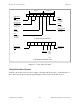
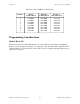
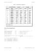
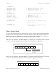
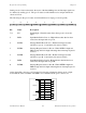

Table Of Contents
- PC-DIO-24 User Manual
- Contents
- About This Manual
- Chapter 1 Introduction
- Chapter 2 Configuration and Installation
- Chapter 3 Theory of Operation
- Chapter 4 Register-Level Programming
- Appendix A Specifications
- Appendix B I/O Connector
- Appendix C OKI 82C55A Data Sheet*
- Appendix D Customer Communication
- Glossary
- Index
- Figures
- Figure 1-1. The Relationship between the Programming Environment, NI-DAQ, and Your Hardware
- Figure 2-1. PC-DIO-24 Parts Locator Diagram
- Figure 2-2. Example Base I/O Address Switch Settings
- Figure 2-3. Jumper Settings–PC6, PC4, PC2, and N/C
- Figure 2-4. Interrupt Jumper Setting for IRQ5 (Factory Setting)
- Figure 2-5. Digital I/O Connector Pin Assignments
- Figure 3-1. PC-DIO-24 Block Diagram
- Figure 4-1. Control-Word Formats
- Figure B-1. PC-DIO-24 I/O Connector
- Tables
- Table 2-1. PC-DIO-24 Factory-Set Jumper and Switch Settings
- Table 2-2. Port C Signal Assignments
- Table 4-1. PC-DIO-24 Address Map
- Table 4-2. Port C Set/Reset Control Words
- Table 4-3. Mode 0 I/O Configurations
- Table 4-4. Interrupt Enable Signals for All Mode Combinations
- Table A-1. Maximum Average Transfer Rates for the PC-DIO-24

Chapter 4 Register-Level Programming
© National Instruments Corporation 4-5 PC-DIO-24 User Manual
Table 4-2. Port C Set/Reset Control Words
Number Bit Set Bit Reset Bit Set or
Control Word Control Word Reset in Port C
0 0xxx0001 0xxx0000 xxxxxxxn
1 0xxx0011 0xxx0010 xxxxxxnx
2 0xxx0101 0xxx0100 xxxxxnxx
3 0xxx0111 0xxx0110 xxxxnxxx
4 0xxx1001 0xxx1000 xxxnxxxx
5 0xxx1011 0xxx1010 xxnxxxxx
6 0xxx1101 0xxx1100 xnxxxxxx
7 0xxx1111 0xxx1110 nxxxxxxx
Programming Considerations
Mode 0–Basic I/O
Mode 0 can be used for simple I/O functions for each of the three ports with no handshaking.
Each port can be assigned as an input or an output port. The 16 possible I/O configurations are
shown in Table 4-3. Notice that bit 7 of the control word is set when programming the mode of
operation for each port.