
Network Card User Manual
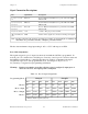
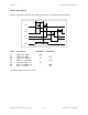
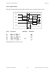
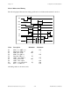
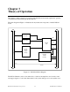
Table Of Contents
- PC-DIO-24 User Manual
- Contents
- About This Manual
- Chapter 1 Introduction
- Chapter 2 Configuration and Installation
- Chapter 3 Theory of Operation
- Chapter 4 Register-Level Programming
- Appendix A Specifications
- Appendix B I/O Connector
- Appendix C OKI 82C55A Data Sheet*
- Appendix D Customer Communication
- Glossary
- Index
- Figures
- Figure 1-1. The Relationship between the Programming Environment, NI-DAQ, and Your Hardware
- Figure 2-1. PC-DIO-24 Parts Locator Diagram
- Figure 2-2. Example Base I/O Address Switch Settings
- Figure 2-3. Jumper Settings–PC6, PC4, PC2, and N/C
- Figure 2-4. Interrupt Jumper Setting for IRQ5 (Factory Setting)
- Figure 2-5. Digital I/O Connector Pin Assignments
- Figure 3-1. PC-DIO-24 Block Diagram
- Figure 4-1. Control-Word Formats
- Figure B-1. PC-DIO-24 I/O Connector
- Tables
- Table 2-1. PC-DIO-24 Factory-Set Jumper and Switch Settings
- Table 2-2. Port C Signal Assignments
- Table 4-1. PC-DIO-24 Address Map
- Table 4-2. Port C Set/Reset Control Words
- Table 4-3. Mode 0 I/O Configurations
- Table 4-4. Interrupt Enable Signals for All Mode Combinations
- Table A-1. Maximum Average Transfer Rates for the PC-DIO-24
Configuration and Installation Chapter 2
PC-DIO-24 User Manual 2-8 © National Instruments Corporation
Timing Specifications
This section lists the timing specifications for handshaking with the PC-DIO-24. The
handshaking lines STB* and IBF synchronize input transfers. The handshaking lines OBF* and
ACK* synchronize output transfers.
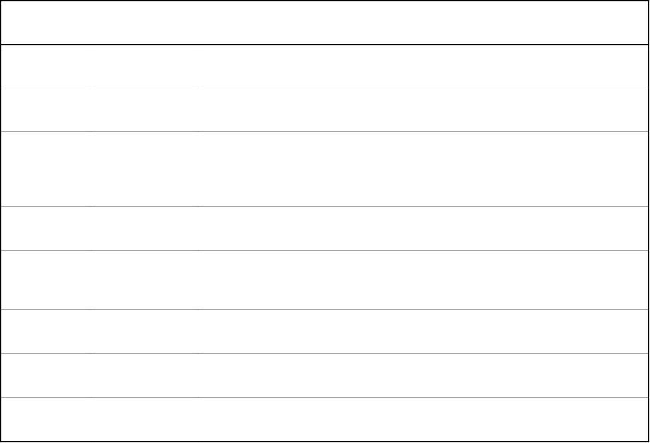
The following signals are used in the timing diagrams on the subsequent pages.
Name Signal
Direction
Description
STB* Input Strobe Input—A low signal on this handshaking line loads data into the input
latch.
IBF Output Input Buffer Full—A high signal on this handshaking line indicates that data
has been loaded into the input latch. This is an input acknowledge signal.
ACK* Input Acknowledge Input—A low signal on this handshaking line indicates that
the data written from the selected port has been accepted. This signal is a
response from the external device that it has received the data from the
PC-DIO-24.
OBF* Output Output Buffer Full—A low signal on this handshaking line indicates that
data has been written from the selected port.
INTR Output Interrupt Request—This signal becomes high when the 82C55A is
requesting service during a data transfer. The appropriate interrupt enable
bits must be set to generate this signal.
RD* Internal Read Signal—This signal is the read signal generated from the control lines
of the PC.
WR* Internal Write Signal—This signal is the write signal generated from the control lines
of the PC.
DATA Bidirectional Data Lines at the Selected Port—This signal indicates when the data on the
data lines at a selected port is or should be available.