
Network Card User Manual


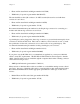


Table Of Contents
- PC-DIO-24 User Manual
- Contents
- About This Manual
- Chapter 1 Introduction
- Chapter 2 Configuration and Installation
- Chapter 3 Theory of Operation
- Chapter 4 Register-Level Programming
- Appendix A Specifications
- Appendix B I/O Connector
- Appendix C OKI 82C55A Data Sheet*
- Appendix D Customer Communication
- Glossary
- Index
- Figures
- Figure 1-1. The Relationship between the Programming Environment, NI-DAQ, and Your Hardware
- Figure 2-1. PC-DIO-24 Parts Locator Diagram
- Figure 2-2. Example Base I/O Address Switch Settings
- Figure 2-3. Jumper Settings–PC6, PC4, PC2, and N/C
- Figure 2-4. Interrupt Jumper Setting for IRQ5 (Factory Setting)
- Figure 2-5. Digital I/O Connector Pin Assignments
- Figure 3-1. PC-DIO-24 Block Diagram
- Figure 4-1. Control-Word Formats
- Figure B-1. PC-DIO-24 I/O Connector
- Tables
- Table 2-1. PC-DIO-24 Factory-Set Jumper and Switch Settings
- Table 2-2. Port C Signal Assignments
- Table 4-1. PC-DIO-24 Address Map
- Table 4-2. Port C Set/Reset Control Words
- Table 4-3. Mode 0 I/O Configurations
- Table 4-4. Interrupt Enable Signals for All Mode Combinations
- Table A-1. Maximum Average Transfer Rates for the PC-DIO-24

Configuration and Installation Chapter 2
PC-DIO-24 User Manual 2-2 © National Instruments Corporation
4 3
21
NATIONAL
INSTRUMENTS
1U2
2W1
3F1
4W2
Figure 2-1. PC-DIO-24 Parts Locator Diagram
Base I/O Address Settings
The base I/O address for the PC-DIO-24 is determined by the switches at position U2 (see
Figure 2-1). The switches are set at the factory for the I/O address hex 210. With this default
setting, the PC-DIO-24 uses the I/O address space hex 210 through 213.
Note: Verify that this space is not already used by other equipment installed in your
computer. If any equipment in your computer uses this I/O address space, you must
change the base I/O address for the PC-DIO-24 or for the other device.
Each switch in U2 corresponds to one of the address lines A9 through A2. Thus, the range for
possible base I/O address settings is hex 000 through 3FC. Base I/O address values hex 000
through 0FF are reserved for system use. Base I/O values hex 100 through 3FF are available on
the I/O channel. A1 and A0 are used by the PC-DIO-24 to decode the onboard registers. On the