PC-DIO-24 User Manual Digital I/O Board for the IBM PC/XT/AT September 1995 Edition Part Number 320288B-01 © Copyright 1989, 1995 National Instruments Corporation. All Rights Reserved.
National Instruments Corporate Headquarters 6504 Bridge Point Parkway Austin, TX 78730-5039 (512) 794-0100 Technical support fax: (800) 328-2203 (512) 794-5678 Branch Offices: Australia 03 9 879 9422, Austria 0662 45 79 90 0, Belgium 02 757 00 20, Canada (Ontario) 519 622 9310, Canada (Québec) 514 694 8521, Denmark 45 76 26 00, Finland 90 527 2321, France 1 48 14 24 24, Germany 089 741 31 30, Hong Kong 2645 3186, Italy 02 48301892, Japan 03 5472 2970, Korea 02 596 7456, Mexico 5 202 2544, Netherlands 03480
Limited Warranty The PC-DIO-24 is warranted against defects in materials and workmanship for a period of one year from the date of shipment, as evidenced by receipts or other documentation. National Instruments will, at its option, repair or replace equipment that proves to be defective during the warranty period. This warranty includes parts and labor.
WARNING REGARDING MEDICAL AND CLINICAL USE OF NATIONAL INSTRUMENTS PRODUCTS National Instruments products are not designed with components and testing intended to ensure a level of reliability suitable for use in treatment and diagnosis of humans. Applications of National Instruments products involving medical or clinical treatment can create a potential for accidental injury caused by product failure, or by errors on the part of the user or application designer.
FCC/DOC Radio Frequency Interference Compliance This equipment generates and uses radio frequency energy and, if not installed and used in strict accordance with the instructions in this manual, may cause interference to radio and television reception. This equipment has been tested and found to comply with the following two regulatory agencies: Federal Communications Commission This device complies with Part 15 of the Federal Communications Commission (FCC) Rules for a Class A digital device.
Contents About This Manual .............................................................................................................xi Organization of This Manual .........................................................................................xi Conventions Used in This Manual .................................................................................xii National Instruments Documentation ............................................................................
Contents Chapter 4 Register-Level Programming .........................................................................................4-1 Introduction ....................................................................................................................4-1 82C55A Modes of Operation .........................................................................................4-1 Mode 0 ...............................................................................................................
Contents Figures Figure 1-1. The Relationship between the Programming Environment, NI-DAQ, and Your Hardware...................................................................................................1-3 Figure 2-1. Figure 2-2. Figure 2-3. Figure 2-4. Figure 2-5. PC-DIO-24 Parts Locator Diagram ...................................................................2-2 Example Base I/O Address Switch Settings .....................................................
About This Manual This manual describes the mechanical and electrical aspects of the PC-DIO-24 and contains information concerning its operation and programming. The PC-DIO-24 is a 24-bit parallel, digital I/O interface designed around an 82C55A programmable peripheral interface (PPI). The PC-DIO-24 is a member of the National Instruments PC Series of PC I/O Channel expansion boards for the IBM PC computer family.
About This Manual • The Index alphabetically lists the topics in this manual, including the page where you can find each one. Conventions Used in This Manual The following conventions are used in this manual. bold Bold text denotes menus, menu items, or dialog box buttons or options. bold italic Bold italic text denotes a note, caution, or warning. italic Italic text denotes emphasis, a cross reference, or an introduction to a key concept.
About This Manual • Your SCXI hardware user manuals—If you are using SCXI, read these manuals next for detailed information about signal connections and module configuration. They also explain in greater detail how the module works and contain application hints. • Your DAQ hardware user manuals—These manuals have detailed information about the DAQ hardware that plugs into or is connected to your computer.
Chapter 1 Introduction This chapter describes the PC-DIO-24, lists what you need to get started, describes software programming choices, optional equipment, and custom cables, and explains how to unpack the PC-DIO-24. About the PC-DIO-24 Thank you for purchasing the National Instruments PC-DIO-24. The PC-DIO-24 is a low cost, 24-bit parallel, digital I/O interface for the PC. An OKI 82C55A PPI controls the 24 bits of digital I/O.
Introduction Chapter 1 With the PC-DIO-24, the PC can serve as a digital I/O system controller for laboratory testing, production testing, and industrial process monitoring and control. Detailed specifications of the PC-DIO-24 are in Appendix A, Specifications.
Chapter 1 Introduction NI-DAQ Driver Software The NI-DAQ driver software is included at no charge with all National Instruments DAQ hardware. NI-DAQ is not packaged with SCXI or accessory products, except for the SCXI-1200. NI-DAQ has an extensive library of functions that you can call from your application programming environment.
Introduction Chapter 1 Register-Level Programming The final option for programming any National Instruments DAQ hardware is to write registerlevel software. Writing register-level programming software can be very time-consuming and inefficient, and is not recommended for most users. Even if you are an experienced register-level programmer, consider using NI-DAQ, LabVIEW, or LabWindows/CVI to program your National Instruments DAQ hardware.
Chapter 1 Introduction • Electronic Products Division/3M (part number 3425-7650) • T&B/Ansley Corporation (part number 609-5041CE) The standard ribbon cable (50-conductor, 28 AWG, stranded) that can be used with these connectors is as follows: • Electronic Products Division/3M (part number 3365/50) • T&B/Ansley Corporation (part number 171-50) Recommended manufacturer part numbers for the 50-pin edge connector for connecting to a module rack with an edge connector are as follows: • Electronic Pro
Introduction Chapter 1 Unpacking Your PC-DIO-24 board is shipped in an antistatic package to prevent electrostatic damage to the board. Electrostatic discharge can damage several components on the board. To avoid such damage in handling the board, take the following precautions: • Ground yourself via a grounding strap or by holding a grounded object. • Touch the antistatic package to a metal part of your PC chassis before removing the board from the package.
Chapter 2 Configuration and Installation This chapter describes how to configure and install the PC-DIO-24, including I/O connector signal descriptions, handshake timing diagrams, and cabling instructions. Board Configuration The PC-DIO-24 contains one DIP switch and two jumpers to configure the base I/O address and interrupts, respectively. The PC-DIO-24 also contains one fuse to protect the +5 V power output. Figure 2-1 shows the location of jumper sets W1 and W2, DIP switch U2, and the fuse F1.
Configuration and Installation Chapter 2 1 2 NATIONAL INSTRUMENTS 4 1 2 3 4 3 U2 W1 F1 W2 Figure 2-1. PC-DIO-24 Parts Locator Diagram Base I/O Address Settings The base I/O address for the PC-DIO-24 is determined by the switches at position U2 (see Figure 2-1). The switches are set at the factory for the I/O address hex 210. With this default setting, the PC-DIO-24 uses the I/O address space hex 210 through 213.
Chapter 2 Configuration and Installation A8 A7 A6 A5 A4 A3 A2 O N A9 U2 DIP switches, press the side marked OFF to select a binary value of 1 for the corresponding address bit. Press the other side of the switch to select a binary value of 0 for the corresponding address bit. Figure 2-2 shows two possible switch settings. The black side indicates the side that is pushed down. 1 2 3 4 5 6 7 8 O F F U2 A8 A7 A6 A5 A4 A3 A2 O N A9 A.
Configuration and Installation Chapter 2 Interrupt Selection There are two sets of jumpers for interrupt selection on the PC-DIO-24 board. W1 is used for selecting the interrupt enable line. W2 is for selecting the interrupt level. The location of these jumpers is shown in Figure 2-1. Interrupt Enable Settings To enable interrupt requests from the PC-DIO-24, you must set jumper W1 to select PC2, PC4, or PC6 as the active low interrupt enable line.
Chapter 2 Configuration and Installation The PC-DIO-24 can share interrupt lines with other devices by using a tristate driver to drive its selected interrupt lines. Installation The PC-DIO-24 can be installed in any unused 8-bit or 16-bit expansion slot in your computer. After you make any necessary changes and verify the switch and jumper settings, record the settings in the PC-DIO-24 Hardware and Software Configuration Form in Appendix D, Customer Communication.
Configuration and Installation Chapter 2 Signal Connections I/O Connector Pin Description Figure 2-5 shows the pin assignments for the PC-DIO-24 digital I/O connector. Warning: Connections that exceed any of the maximum ratings of input or output signals on the PC-DIO-24 may result in damage to the PC-DIO-24 board and to the PC. Maximum ratings for each signal are given in this chapter under the discussion of that signal.
Chapter 2 Configuration and Installation Signal Connection Descriptions Pin Signal Name Description 1, 3, 5, 7, 9, 11, 13, 15 PC<7..0> Port C—Bidirectional data lines for port C. PC7 is the MSB, PC0 the LSB. 17, 19, 21, 23, 25, 27, 29, 31 PB<7..0> Port B—Bidirectional data lines for port B. PB7 is the MSB, PB0 the LSB. 33, 35, 37, 39, 41, 43, 45, 47 PA<7..0> Port A—Bidirectional data lines for port B. PA7 is the MSB, PA0 the LSB. 49 (see note below) +5 V +5 Volts—This pin provides +5 VDC.
Configuration and Installation Chapter 2 Timing Specifications This section lists the timing specifications for handshaking with the PC-DIO-24. The handshaking lines STB* and IBF synchronize input transfers. The handshaking lines OBF* and ACK* synchronize output transfers. The following signals are used in the timing diagrams on the subsequent pages. Name Signal Direction Description STB* Input Strobe Input—A low signal on this handshaking line loads data into the input latch.
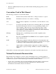
Chapter 2 Configuration and Installation Mode 1 Input Timing The following figure illustrates the timing specifications for an input transfer in mode 1. T1 T2 T4 STB* T7 IBF T6 INTR RD* T5 T3 DATA Name Description T1 T2 T3 T4 T5 T6 T7 STB* pulse width STB* = 0 to IBF = 1 Data before STB* = 1 STB* = 1 to INTR = 1 Data after STB* = 1 RD* = 0 to INTR = 0 RD* = 1 to IBF = 0 Minimum Maximum 100 – 20 – 50 – – – 150 – 150 – 200 150 All timing values are in nanoseconds.
Configuration and Installation Chapter 2 Mode 1 Output Timing The following figure illustrates the timing specifications for an output transfer in mode 1. T3 WR* T4 OBF* T1 T6 INTR T5 ACK* DATA T2 Name Description T1 T2 T3 T4 T5 T6 WR* = 0 to INTR = 0 WR* = 1 to output WR* = 1 to OBF* = 0 ACK* = 0 to OBF* = 1 ACK* pulse width ACK* = 1 to INTR = 1 Minimum Maximum – – – – 100 – 250 200 150 150 – 150 All timing values are in nanoseconds.
Chapter 2 Configuration and Installation Mode 2 Bidirectional Timing The following figure illustrates the timing specifications for bidirectional transfers in mode 2.
Chapter 3 Theory of Operation This chapter contains a functional overview of the PC-DIO-24 board and explains the operation of each functional unit making up the PC-DIO-24. The block diagram in Figure 3-1 illustrates the key functional components of the PC-DIO-24 board. Address Decoder PA / 8 PC I/O Channel 82C55A PPI PB / 8 PC / 8 PC I/O Channel Control Circuitry Interrupt Control Circuitry I/O Connector Bus Transceivers PC3 PC0 +5 V 1 A Fuse Figure 3-1.
Theory of Operation Chapter 3 Address Decoder The base address used by the board is determined by an onboard switch setting. The address on the PC I/O Channel bus is monitored by the address decoder. If the address on the bus matches the selected I/O base address of the board, the board is enabled and the corresponding register on the PC-DIO-24 is accessed. Bus Transceivers The bus transceivers control the sending and receiving of data lines to and from the PC I/O Channel.
Chapter 4 Register-Level Programming This chapter describes in detail the address and function of each of the PC-DIO-24 control and status registers. This chapter also includes important information related to register-level programming the PC-DIO-24. The PC-DIO-24 is a parallel, digital I/O board designed around the OKI 82C55A integrated circuit. The 82C55A is a general-purpose peripheral interface containing 24 programmable I/O pins.
Register-Level Programming Chapter 4 Mode 0 This mode can be used for simple input and output operations for each of the ports. No handshaking is required; data is simply written to or read from a selected port. Mode 0 has the following features: • Two 8-bit ports (A and B) and two 4-bit ports (upper and lower nibble of port C). • Any port can be input or output. • Outputs are latched, but inputs are not latched. Mode 1 This mode transfers data that is synchronized by handshaking signals.
Chapter 4 Register-Level Programming Register Map The following table lists the address map for the PC-DIO-24. The registers PORTA, PORTB, PORTC, and CNFG are 8-bit registers in the 82C55A. Table 4-1. PC-DIO-24 Address Map Register Offset Address (Hex) PORTA PORTB PORTC CNFG Size 8-bit 8-bit 8-bit 8-bit 0x00 0x01 0x02 0x03 Type Read-and-write Read-and-write Read-and-write Write-Only Note: A number preceded by 0x is a hexadecimal number.
Register-Level Programming Chapter 4 Group A D7 D6 D5 Group B D4 D3 D2 D1 D0 Control Word Flag Port C (low nibble) 1 = input 0 = output 1 = mode set Mode Selection 00 = mode 0 01 = mode 1 1X = mode 2 Port B 1 = input 0 = output Mode Selection 0 = mode 0 1 = mode 1 Port A 1 = input 0 = output Port C (high nibble) 1 = input 0 = output a.
Chapter 4 Register-Level Programming Table 4-2.
Register-Level Programming Chapter 4 Table 4-3.
Chapter 4 Register-Level Programming /* EXAMPLE 1*/ outp(cnfg,0x80); outp(porta,0x12); outp(portb,0x34); outp(portc,0x56); /* /* /* /* /* EXAMPLE 2*/ outp(cnfg,0x90); Ports Write Write Write A, B, and C are data to port A. data to port B. data to port C. outputs. */ */ */ */ /* Port A is input; ports B and C are outputs. */ /* Write data to port B. */ /* Write data to port C. */ /* Read data from port A.
Register-Level Programming Chapter 4 During a mode 1 data read transfer, the status of the handshaking lines and interrupt signals can be obtained by reading port C. The port C status-word bit definitions for an input transfer are shown as follows. The following are the port C status-word bit definitions for input (port A and port B).
Chapter 4 Register-Level Programming Mode 1 Input Programming Example Main() { #define #define #define #define #define BASE_ADDRESS PORTAoffset PORTBoffset PORTCoffset CNFGoffset 0x210 0x00 0x01 0x02 0x03 /* /* /* /* /* Board located at address 210. */ Offset for port A */ Offset for port B */ Offset for port C */ Offset for CNFG */ register unsigned int porta, portb, portc, cnfg; char valread; /* Variable to store data read from a port */ /* Calculate register addresses.
Register-Level Programming Chapter 4 The control word written to the CNFG Register to configure port B for output in mode 1 is shown as follows. Notice that port B does not have extra input or output lines from port C. 7 6 5 4 3 2 1 0 1 X X X X 1 0 X During a mode 1 data write transfer, the status of the handshaking lines and interrupt signals can be obtained by reading port C. Notice that the bit definitions are different for a write and a read transfer.
Chapter 4 Register-Level Programming At the digital I/O connector, port C has the following pin assignments when in mode 1 output. Notice that the status of ACKA* and ACKB* is not included when port C is read.
Register-Level Programming Chapter 4 Mode 2–Bidirectional Bus Mode 2 has an 8-bit bus that can transfer both input and output without changing the configuration. The data transfers are synchronized with handshaking lines in port C. This mode uses only port A; however, port B can be used in either mode 0 or mode 1 while port A is configured for mode 2. The control word written to the CNFG Register to configure port A as a bidirectional data bus in mode 2 is shown as follows.
Chapter 4 Register-Level Programming Bit Name Description (continued) 4 INTE2 Interrupt Enable Bit for Input—If this bit is set, interrupts are enabled from the 82C55A for IBFA. Controlled by bit set/reset of PC4. 3 INTRA Interrupt Request Status—If INTE1 is high and IBFA is high, this bit is high, indicating that an interrupt request is asserted for input transfers. If INTE2 is high and OBFA* is high, this bit is high, indicating that an interrupt request is asserted for output transfers.
Register-Level Programming Chapter 4 /* EXAMPLE 1*/ outp(cnfg,0xC0); while (!(inp(portc) & 0x80)); /* Port A is in mode 2. */ /* Wait until OBFA* is set, indicating that the data last written to port A has been read.*/ /* Write the data to port A. */ /* Wait until IBFA is set, indicating that data is available in port A to be read. */ /* Read data from port A.
Chapter 4 Register-Level Programming /* EXAMPLE 3–Set up interrupts for mode 1 output for port A. the interrupt enable bit. */ outp(cnfg,0xA0); outp(cnfg,0x0D); outp(cnfg,0x0C); Select PC4 as /* Port A is an output in mode 1. */ /* Set PC6 to enable interrupts from 82C55A. */ /* Clear PC4 to enable interrupts. */ /* EXAMPLE 4–Set up interrupts for mode 1 output for port B. the interrupt enable bit. */ outp(cnfg,0x84); outp(cnfg,0x05); outp(cnfg,0x08); /* Port B is an output in mode 1.
Register-Level Programming Chapter 4 Table 4-4.
Appendix A Specifications This appendix lists the specifications for the PC-DIO-24 board. These specifications are typical at 25° C, unless otherwise stated. The operating temperature range is 0° to 70° C. Digital I/O Number of channels .................................................... 24 I/O Compatibility .............................................................. TTL Absolute max voltage input rating .............................. -0.5 to +5.5 V with respect to GND Handshaking .....................
Specifications Appendix A Physical Dimensions .................................................................. 17.5 by 9.9 cm (6.9 in. by 3.9 in.) I/O connector............................................................... 50-pin male ribbon-cable connector Power Requirement (from PC I/O Channel) Typ power ................................................................... 0.10 A at 5 VDC (±10%) Max power .................................................................. 0.
Appendix B I/O Connector This appendix describes the pinout and signal names for the I/O connector on the PC-DIO-24. Figure B-1 shows the PC-DIO-24 digital I/O connector.
Appendix OKI 82C55A Data Sheet* C This appendix contains the manufacturer data sheet for the OKI Semiconductor 82C55A CMOS programmable peripheral interface (PPI). This interface is used on the DAQCard-DIO-24. * Copyright © OKI Semiconductor. 1993. Reprinted with permission of copyright owner. All rights reserved. OKI Semiconductor Data Book Microprocessor, Seventh Edition, March 1993.
Appendix C OKI 82C55A Data Sheet PC-DIO-24 User Manual C-2 © National Instruments Corporation
Appendix C © National Instruments Corporation C-3 OKI 82C55A Data Sheet PC-DIO-24 User Manual
Appendix C OKI 82C55A Data Sheet PC-DIO-24 User Manual C-4 © National Instruments Corporation
Appendix C © National Instruments Corporation C-5 OKI 82C55A Data Sheet PC-DIO-24 User Manual
Appendix C OKI 82C55A Data Sheet PC-DIO-24 User Manual C-6 © National Instruments Corporation
Appendix C © National Instruments Corporation C-7 OKI 82C55A Data Sheet PC-DIO-24 User Manual
Appendix C OKI 82C55A Data Sheet PC-DIO-24 User Manual C-8 © National Instruments Corporation
Appendix C © National Instruments Corporation C-9 OKI 82C55A Data Sheet PC-DIO-24 User Manual
Appendix C OKI 82C55A Data Sheet PC-DIO-24 User Manual C-10 © National Instruments Corporation
Appendix C © National Instruments Corporation C-11 OKI 82C55A Data Sheet PC-DIO-24 User Manual
Appendix C OKI 82C55A Data Sheet PC-DIO-24 User Manual C-12 © National Instruments Corporation
Appendix C © National Instruments Corporation C-13 OKI 82C55A Data Sheet PC-DIO-24 User Manual
Appendix C OKI 82C55A Data Sheet PC-DIO-24 User Manual C-14 © National Instruments Corporation
Appendix C © National Instruments Corporation C-15 OKI 82C55A Data Sheet PC-DIO-24 User Manual
Appendix C OKI 82C55A Data Sheet PC-DIO-24 User Manual C-16 © National Instruments Corporation
Appendix C © National Instruments Corporation C-17 OKI 82C55A Data Sheet PC-DIO-24 User Manual
Appendix D Customer Communication ___________________________________________________ For your convenience, this appendix contains forms to help you gather the information necessary to help us solve technical problems you might have as well as a form you can use to comment on the product documentation. Filling out a copy of the Technical Support Form before contacting National Instruments helps us help you better and faster. National Instruments provides comprehensive technical assistance around the world.
Technical Support Form ___________________________________________________ Photocopy this form and update it each time you make changes to your software or hardware, and use the completed copy of this form as a reference for your current configuration. Completing this form accurately before contacting National Instruments for technical support helps our applications engineers answer your questions more efficiently.
PC-DIO-24 Hardware and Software Configuration Form ___________________________________________________ Record the settings and revisions of your hardware and software on the line to the right of each item. Complete a new copy of this form each time you revise your software or hardware configuration, and use this form as a reference for your current configuration.
Documentation Comment Form ___________________________________________________ National Instruments encourages you to comment on the documentation supplied with our products. This information helps us provide quality products to meet your needs. Title: PC-DIO-24 User Manual Edition Date: September 1995 Part Number: 320288B-01 Please comment on the completeness, clarity, and organization of the manual. If you find errors in the manual, please record the page numbers and describe the errors.
Glossary ___________________________________________________ ° Ω % A AWG BCD C DMA hex Hz in.
Index (table), 4-5 custom cables, 1-4 to 1-5 customer communication, xiii, D-1 Special Characters +5 V signal (table), 2-7 82C55A Programmable Peripheral Interface. See OKI 82C55A Programmable Peripheral Interface.
Index I interrupt enable settings, 2-4 interrupt handling, 4-15 to 4-16 recommended jumper settings for W1, 4-16 interrupt level settings, 2-4 to 2-5 IBF signal description (table), 2-8 mode 1 input timing, 2-9 mode 2 bidirectional timing, 2-11 IBFA bit, Port C, 4-8, 4-12 IBFB bit, Port C, 4-8 installation. See also configuration.
Index N register-level programming, 1-4 theory of operation, 3-1 to 3-2 unpacking, 1-6 physical specifications, A-2 Port C pin assignments description, 2-7 mode 1 input (figure), 4-8 mode 1 output (figure), 4-11 mode 2 bidirectional bus (figure), 4-13 signal assignments (table), 2-7 set/reset control words (table), 4-5 status-word bit definitions mode 1 strobed input, 4-8 mode 1 strobed output, 4-10 mode 2 bidirectional bus (figure), 4-12 to 4-13 power requirements (from PC I/O channel), A-2 programming.
Index environment, A-1 physical, A-2 power requirements (from PC I/O channel), A-2 transfer rates, A-2 SSR-OAC-5 and SSR-OAC-5A output modules, driving with PC-DIO-24 (note), 1-1 STB* signal description (table), 2-8 mode 1 input timing, 2-9 mode 2 bidirectional timing, 2-11 switch settings. See jumper and switch settings.