Click here to comment on this document via the National Instruments website at www.natinst.com/documentation/daq PC-DIO-24/PnP User Manual 24-bit Digital I/O Board for ISA Computers February 1998 Edition Part Number 320288C-01 © Copyright 1989, 1998 National Instruments Corporation. All rights reserved.
Internet Support E-mail: support@natinst.com FTP Site: ftp.natinst.com Web Address: http://www.natinst.
Important Information Warranty The PC-DIO-24 and PC-DIO-24PnP boards are warranted against defects in materials and workmanship for a period of one year from the date of shipment, as evidenced by receipts or other documentation. National Instruments will, at its option, repair or replace equipment that proves to be defective during the warranty period. This warranty includes parts and labor.
FCC/DOC Radio Frequency Interference Class A Compliance This equipment generates and uses radio frequency energy and, if not installed and used in strict accordance with the instructions in this manual, may cause interference to radio and television reception. Classification requirements are the same for the Federal Communications Commission (FCC) and the Canadian Department of Communications (DOC).
Contents About This Manual Organization of This Manual ........................................................................................ ix Conventions Used in This Manual................................................................................ x National Instruments Documentation ........................................................................... xii Related Documentation.................................................................................................
Contents Digital I/O Power-up State Selection ........................................................................... 3-7 High DIO Power-up State .............................................................................. 3-7 Low DIO Power-up State............................................................................... 3-9 Timing Specifications................................................................................................... 3-10 Mode 1 Input Timing ..........................
Contents Mode 1—Strobed Input.................................................................................. C-11 Mode 1 Input Programming Example.............................................. C-13 Mode 1—Strobed Output ............................................................................... C-14 Mode 1 Output Programming Example ........................................... C-16 Mode 2—Bidirectional Bus............................................................................
Contents Figure 3-7. Mode 2 Timing Specification for Bidirectional Transfers .................... 3-14 Figure 4-1. PC-DIO-24/PnP Block Diagram ........................................................... 4-1 Figure C-1. Figure C-2. Figure C-3. Figure C-4. Figure C-5. Control Word Formats for the 82C55A ................................................ C-4 Port C Pin Assignments, Mode 1 Input ................................................. C-13 Port C Pin Assignments, Mode 1 Output ....................
About This Manual This manual describes the mechanical and electrical aspects of the PC-DIO-24/PnP and contains information concerning its operation and programming. The PC-DIO-24/PnP is a member of the National Instruments family of I/O channel expansion boards for ISA computers. These boards are designed for high-performance, low-cost data acquisition and control for applications in laboratory testing, production testing, and industrial process monitoring and control.
About This Manual • Appendix C, Register-Level Programming, describes in detail the address and function of each of the PC-DIO-24/PnP control and status registers. • Appendix D, Using Your PC-DIO-24 (Non-PnP) Board, describes the differences between the PC-DIO-24 and PC-DIO-24PnP boards, the PC-DIO-24 board configuration, and the PC-DIO-24 installation into your computer.
About This Manual monospace Text in this font denotes text or characters that you should enter literally from the keyboard, sections of code, programming examples, and syntax examples. This font is also used for the proper names of disk drives, paths, directories, programs, subprograms, subroutines, device names, functions, operations, variables, filenames and extensions, and for statements and comments taken from programs.
About This Manual National Instruments Documentation The PC-DIO-24/PnP User Manual is one piece of the documentation set for your data acquisition (DAQ) system. You could have any of several types of manuals, depending on the hardware and software in your system. Use the different types of manuals you have as follows: PC-DIO-24/PnP User Manual • Getting Started with SCXI—If you are using SCXI, this is the first manual you should read.
About This Manual Related Documentation The following documents contain information that you may find helpful as you read this manual: • Your computer technical reference manual • Plug and Play ISA Specification Customer Communication National Instruments wants to receive your comments on our products and manuals. We are interested in the applications you develop with our products, and we want to help if you have problems with them.
Chapter 1 Introduction This chapter describes the PC-DIO-24/PnP, lists what you need to get started, describes software programming choices, optional equipment, and custom cables, and explains how to unpack the PC-DIO-24/PnP. About the PC-DIO-24/PnP Thank you for purchasing the National Instruments PC-DIO-24/PnP. The PC-DIO-24/PnP is a low cost, 24-bit, parallel digital I/O interface for ISA computers. An OKI 82C55A programmable peripheral interface (PPI) chip controls the 24 bits of digital I/O.
Chapter 1 Introduction What You Need to Get Started To set up and use your PC-DIO-24/PnP, you will need the following: ❑ PC-DIO-24PnP or PC-DIO-24 board ❑ PC-DIO-24/PnP User Manual ❑ One of the following software packages and documentation: BridgeVIEW ComponentWorks LabVIEW for Windows LabWindows/CVI Measure NI-DAQ for PC compatibles VirtualBench ❑ Your computer Software Programming Choices You have several options to choose from when programming your National Instruments DAQ and SCXI hardware.
Chapter 1 Introduction LabWindows/CVI features interactive graphics and a state-of-the-art user interface and uses the ANSI standard C programming language. The LabWindows/CVI Data Acquisition Library, a series of functions for using LabWindows/CVI with National Instruments DAQ hardware, is included with the NI-DAQ software kit. The LabWindows/CVI Data Acquisition Library is functionally equivalent to the NI-DAQ software.
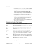
Chapter 1 Introduction Conventional Programming Environment ComponentWorks, LabVIEW, LabWindows/CVI, or VirtualBench NI-DAQ Driver Software DAQ or SCXI Hardware Personal Computer or Workstation Figure 1-1. The Relationship between the Programming Environment, NI-DAQ, and Your Hardware Register-Level Programming The final option for programming any National Instruments DAQ hardware is to write register-level software.
Chapter 1 Introduction Optional Equipment National Instruments offers a variety of products to use with your PC-DIO-24/PnP board, including cables, connector blocks, and other accessories, as follows: • Cables and cable assemblies, shielded and ribbon • Connector blocks, shielded and unshielded 50-pin screw terminals • SCXI modules and accessories for isolating, amplifying, exciting, and multiplexing signals for relays and analog output. With SCXI you can condition and acquire up to 3,072 channels.
Chapter 1 Introduction The mating connector for the PC-DIO-24/PnP is a 50-position, polarized, ribbon socket connector with strain relief. National Instruments uses a polarized (keyed) connector to prevent inadvertent upside-down connection to the PC-DIO-24/PnP.
Chapter 1 Introduction Unpacking Your PC-DIO-24/PnP board is shipped in an antistatic package to prevent electrostatic damage to the board. Electrostatic discharge can damage several components on the board. To avoid such damage in handling the board, take the following precautions: • Ground yourself via a grounding strap or by holding a grounded object. • Touch the antistatic package to a metal part of your PC chassis before removing the board from the package.
Chapter Installation and Configuration 2 This chapter describes how to install and configure the PC-DIO-24/PnP. Installation Note: Install your driver software before installing your hardware. Refer to your NI-DAQ release notes for software installation instructions. W1 Figure 2-1. Jumper W1 Location Note: The PC-DIO-24/PnP uses 100 kΩ resistors for polarity selection at power-up.
Chapter 2 Installation and Configuration 1. Turn off and unplug your computer. 2. Remove the I/O channel top cover or access port. 3. Remove the expansion slot cover on the computer back panel. 4. Insert the PC-DIO-24/PnP into any 8- or 16-bit slot. It may be a tight fit, but do not force the board into place. 5. Screw the PC-DIO-24/PnP mounting bracket to the computer back panel rail. 6. Visually verify the installation. 7. Replace the computer cover. 8. Plug in and turn on your computer.
Chapter 2 Installation and Configuration Base I/O Address and Interrupt Selection To change base I/O address or interrupt selection, refer to the NI-DAQ Configuration Utility Help file. You can configure the PC-DIO-24PnP to use base addresses in the range of 100 to 3E0 hex. Each board occupies 32 bytes of address space and must be located on a 32-byte boundary. Therefore, valid addresses include 100, 120, 140…, 3E0 hex. The PC-DIO-24PnP can use interrupt channel 3, 4, 5, 7, or 9.
Chapter 3 Signal Connections This chapter includes timing specifications and signal connection instructions for the PC-DIO-24/PnP I/O connector. ! Caution: Connections that exceed any of the maximum ratings of input or output signals on the PC-DIO-24/PnP can damage the board and the PC. National Instruments is NOT liable for any damages resulting from any such signal connections. Maximum ratings for each signal are given in this chapter under the discussion of that signal.
Chapter 3 Signal Connections PC7 PC6 PC5 PC4 PC3 PC2 PC1 PC0 PB7 PB6 PB5 PB4 PB3 PB2 PB1 PB0 PA7 PA6 PA5 PA4 PA3 PA2 PA1 PA0 +5 V 1 3 2 4 GND GND 5 7 9 6 8 10 GND 11 12 13 14 15 16 GND 17 19 21 23 25 27 29 31 33 35 37 39 41 43 45 47 49 GND 18 20 22 24 26 28 30 32 34 36 38 40 42 44 46 48 50 GND GND GND GND GND GND GND GND GND GND GND GND GND GND GND GND GND GND GND GND Figure 3-1.
Chapter 3 Signal Connections Signal Descriptions Table 3-1 describes the PC-DIO-24/PnP signals. Table 3-1. Signal Descriptions Signal Name Pin Description 1, 3, 5, 7, 9, 11, 13, 15 PC<7..0> Port C—Bidirectional data lines for port C. PC7 is the MSB, PC0 the LSB. 17, 19, 21, 23, 25, 27, 29, 31 PB<7..0> Port B—Bidirectional data lines for port B. PB7 is the MSB, PB0 the LSB. 33, 35, 37, 39, 41, 43, 45, 47 PA<7..0> Port A—Bidirectional data lines for port B. PA7 is the MSB, PA0 the LSB.
Chapter 3 ! Signal Connections Caution: During programming, note that each time you configure any port, output ports A and C are reset to 0, and output port B is undefined. Table 3-2.
Chapter 3 Signal Connections Digital output specifications (referenced to GND): Output logic high voltage (Iol = –2.5 mA) 3.7 V min 5.0 V max Output logic high voltage (Ioh = –4 mA) 2.7 V min 5.0 V max Output logic low voltage (Iol = 2.5 mA) 0 V min 0.4 V Output logic low voltage (Iol = 4 mA) 0 V min 0.5 V Figure 3-2 depicts signal connections for three typical digital I/O applications.
Chapter 3 Signal Connections +5 V +5 V LED Jumper Selectable (W1) 100 kΩ 100 kΩ 100 kΩ 100 kΩ 41 PPI Port A PA<3..0> 43 45 47 100 kΩ 100 kΩ 100 kΩ 100 kΩ 67 69 TTL Signal PPI Port B PB<7..4> 71 73 +5 V Switch 50, 100 GND I/O Connector PC-DIO-24/PnP Figure 3-2. Digital I/O Connections In Figure 3-2, port A is configured for digital output, and port B is configured for digital input.
Chapter 3 Signal Connections Power Connections Pin 49 of the I/O connector is connected to the +5 V supply from the PC power supply. This pin is referenced to GND and can be used to power external digital circuitry. This +5 V supply has a 1 A self-resetting protection fuse in series. Simply remove the circuit causing the heavy current load and the fuse will reset itself. Power rating ! Caution: 1 A at +4.65 to 5.
Chapter 3 Signal Connections PC-DIO-24/PnP +5 V 100 kΩ 82C55A Digital I/O Line RL GND Figure 3-3. DIO Channel Configured for High DIO Power-up State with External Load Example: At power up, the board is configured for input and, by default, all DIO lines are high. To pull one channel low, follow these steps: 1. Install a load (RL). Remember that the smaller the resistance, the greater the current consumption and the lower the voltage. 2.
Chapter 3 Signal Connections Low DIO Power-up State If you select pulled-low mode, each DIO line will be pulled to GND (0 VDC) using a 100 kΩ resistor. To pull a specific line high, connect a pull-up resistor that will give you a minimum of 2.8 VDC. Using the largest possible resistance value ensures that you do not to use more current than necessary to perform the pull-up task, and that the DIO can still drive the line. The DIO lines are capable of sinking a maximum of 2.5 mA at 0.4 V in the low state.
Chapter 3 Signal Connections Therefore: RL = 5.6 kΩ ; 2.2 V / 39 µA This resistor value, 5.6 kΩ, provides a minimum of 2.8 V on the DIO line at power up. You can substitute smaller resistor values but they will draw more current, leaving less sink current for other circuitry connected to this line. The 5.6 kΩ resistor will reduce the amount of a logic low sink current by 0.8 mA with a 0.4 V output.
Chapter 3 Signal Connections Table 3-3. Timing Signal Descriptions (Continued) Name © National Instruments Corporation Signal Direction Description INTR Output Interrupt Request—This signal becomes high when the 82C55A is requesting service during a data transfer. The appropriate interrupt enable bits must be set to generate this signal. RD* Internal Read Signal—This signal is the read signal generated from the control lines of the PC.
Chapter 3 Signal Connections Mode 1 Input Timing The following figure illustrates the timing specifications for an input transfer in mode 1. T1 T2 T4 STB* T7 T6 IBF INTR RD* T3 T5 DATA Name Description Minimum Maximum T1 STB* pulse width 100 — T2 STB* = 0 to IBF* = 1 — 150 T3 Data before STB* = 1 20 — T4 STB* = 1 to INTR = 1 — 150 T5 Data after STB* = 1 50 — T6 RD* = 0 to INTR = 0 — 200 T7 RD* = 1 to IBF = 0 — 150 All timing values are in nanoseconds. Figure 3-5.
Chapter 3 Signal Connections Mode 1 Output Timing The following figure illustrates the timing specifications for an output transfer in mode 1. T3 WR* T4 OBF* T1 T6 INTR T5 ACK* DATA T2 Name Description Minimum Maximum T1 WR* = 0 to INTR = 0 — 250 T2 WR* = 1 to output — 200 T3 WR* = 1 to OBF* = 0 — 150 T4 ACK* = 0 to OBF* = 1 — 150 T5 ACK* pulse width 100 — T6 ACK* = 1 to INTR = 1 — 150 All timing values are in nanoseconds. Figure 3-6.
Chapter 3 Signal Connections Mode 2 Bidirectional Timing The following figure illustrates the timing specifications for bidirectional transfers in mode 2.
Chapter 4 Theory of Operation This chapter contains a functional overview of the PC-DIO-24/PnP board and explains the operation of each functional unit making up the PC-DIO-24/PnP. Functional Overview The block diagram in Figure 4-1 illustrates the key functional components of the PC-DIO-24/PnP board.
Chapter 4 Theory of Operation Bus Transceivers The bus transceivers send and receive data lines and other signals to and from the PC I/O channel. Bus Interface The PC-DIO-24PnP Plug and Play circuitry automatically arbitrates and assigns system resources. Software performs all bus-related configuration, such as setting the board base address and interrupt level. On the PC-DIO-24 (non-PnP), switches and jumpers set the board base address and interrupt level.
Chapter 4 Theory of Operation Digital I/O Connector All digital I/O is transmitted through a standard, 50-pin, male connector. Pin 49 is connected to +5 V through a resettable protection fuse. You can use this +5 V supply to operate I/O module mounting racks. Even-numbered pins are connected to ground. See the Optional Equipment section in Chapter 1, Introduction, as well as Chapter 3, Signal Connections, for additional information.
Appendix A Specifications This appendix lists the specifications for the PC-DIO-24/PnP board. These specifications are typical at 25° C, unless otherwise stated. The operating temperature range is 0° to 70° C. Digital I/O Number of channels ............................24 I/O Compatibility ......................................TTL Absolute max voltage input rating (Vcc = 5.0 V) ......................................–0.5 to +5.5 V with respect to GND Handshaking .......................................
Appendix A Specifications Level Min Max Input high current (Vin = 5 V, W1 set to pulldown) — 65 µA Input logic low current (Vin = 0 V, W1 set to pullup) — –65 µA Input logic low current (Vin = 0 V, W1 set to pulldown) — –11 µA Output Signals Pin 49 (at 4.65 to 5.25 VDC).............. 1.0 A max Level Min Max Output logic high voltage (Iol = –2.5 mA) 3.7 V 5.0 V Output logic high voltage (Ioh = –4 mA) 2.7 V 5.0 V Output logic low voltage (Iol = 2.5 mA) 0V 0.
Appendix A Specifications Environment Operating temperature ........................0° to 70° C Storage temperature ............................–55° to 150° C Relative humidity ...............................5% to 90% noncondensing Transfer Rates Max with NI-DAQ software................50 kbytes/s Constant sustainable rate (typ) ............
Appendix OKI 82C55A Data Sheet B This appendix contains the manufacturer data sheet for the OKI Semiconductor* 82C55A CMOS PPI. This interface is used on the PC-DIO-24/PnP board. * Copyright © OKI Semiconductor 1995. Reprinted with permission of copyright owner. All rights reserved. OKI Semiconductor Data Book Microprocessor, Eighth Edition, January 1995.
Appendix B OKI 82C55A Data Sheet PC-DIO-24/PnP User Manual B-2 © National Instruments Corporation
Appendix B © National Instruments Corporation B-3 OKI 82C55A Data Sheet PC-DIO-24/PnP User Manual
Appendix B OKI 82C55A Data Sheet PC-DIO-24/PnP User Manual B-4 © National Instruments Corporation
Appendix B © National Instruments Corporation B-5 OKI 82C55A Data Sheet PC-DIO-24/PnP User Manual
Appendix B OKI 82C55A Data Sheet PC-DIO-24/PnP User Manual B-6 © National Instruments Corporation
Appendix B © National Instruments Corporation B-7 OKI 82C55A Data Sheet PC-DIO-24/PnP User Manual
Appendix B OKI 82C55A Data Sheet PC-DIO-24/PnP User Manual B-8 © National Instruments Corporation
Appendix B © National Instruments Corporation B-9 OKI 82C55A Data Sheet PC-DIO-24/PnP User Manual
Appendix B OKI 82C55A Data Sheet PC-DIO-24/PnP User Manual B-10 © National Instruments Corporation
Appendix B © National Instruments Corporation B-11 OKI 82C55A Data Sheet PC-DIO-24/PnP User Manual
Appendix B OKI 82C55A Data Sheet PC-DIO-24/PnP User Manual B-12 © National Instruments Corporation
Appendix B © National Instruments Corporation B-13 OKI 82C55A Data Sheet PC-DIO-24/PnP User Manual
Appendix B OKI 82C55A Data Sheet PC-DIO-24/PnP User Manual B-14 © National Instruments Corporation
Appendix B © National Instruments Corporation B-15 OKI 82C55A Data Sheet PC-DIO-24/PnP User Manual
Appendix B OKI 82C55A Data Sheet PC-DIO-24/PnP User Manual B-16 © National Instruments Corporation
Appendix B © National Instruments Corporation B-17 OKI 82C55A Data Sheet PC-DIO-24/PnP User Manual
Appendix Register-Level Programming C This appendix describes in detail the address and function of each of the PC-DIO-24/PnP control and status registers. This appendix also includes important information about register-level programming on the PC-DIO-24/PnP along with program examples written in C and assembly language. Note: If you plan to do application-level programming using software such as LabVIEW, LabWindows/CVI, or NI-DAQ with your PC-DIO-24/PnP board, you need not read this appendix.
Appendix C Register-Level Programming The PC-DIO-24 (non-PnP) does not have interrupt control registers. Instead, it uses one of the port C lines to enable or disable interrupts. See Appendix D, Using Your PC-DIO-24 (Non-PnP) Board for more information. The three 8-bit ports of the 82C55A are divided into two groups of 12 signals each: group A and group B. One 8-bit control word selects the modes of operation for both groups.
Appendix C Register-Level Programming Register Map The following table lists the address map for the PC-DIO-24/PnP. Table C-1.
Appendix C Register-Level Programming Group A D7 D6 D5 Group B D4 D3 D2 D1 D0 Control Word Flag 1 = mode set Port C (low nibble) 1 = input 0 = output Mode Selection 00 = mode 0 01 = mode 1 1X = mode 2 Port B 1 = input 0 = output Mode Selection 0 = mode 0 1 = mode 1 Port A 1 = input 0 = output Port C (high nibble) 1 = input 0 = output a.
Appendix C Register-Level Programming Table C-2 shows the control words for setting or resetting each bit in port C. Notice that bit 7 of the control word is cleared when programming the set/reset option for the bits of port C. Table C-2.
Appendix C Register-Level Programming Interrupt Control Register 1 (PnP Board Only) D7 D6 D5 D4 D3 D2 D1 D0 x x x x x x IRQ1 IRQ0 Bit Name Description 2–7 x Reserved bit. 1 IRQ1 PPI Interrupt Request for Port B—If this bit and the INTEN bit in Interrupt Control Register 2 are both set, the PPI can send an interrupt, INTRB, to the host computer. If this bit is cleared, the PPI does not send the interrupt INTRB to the host computer, regardless of the setting of INTEN.
Appendix C Register-Level Programming Interrupt Control Register 2 (PnP Board Only) D7 D6 D5 D4 D3 D2 D1 D0 X X X X X INTEN X X Bit Name Description 1–0, 3–7 X Reserved Bit. 2 INTEN Global Interrupt Enable Bit—If this bit is set, the PC-DIO-24PnP can interrupt the host computer. If this bit is cleared, the board cannot interrupt the host computer.
Appendix C Register-Level Programming Programming Considerations for the 82C55A Modes of Operation for the 82C55A The three basic modes of operation for the 82C55A are as follows: • Mode 0—Basic I/O • Mode 1—Strobed I/O • Mode 2—Bidirectional bus The 82C55A also has a single bit set/reset feature for port C, which is programmed by the 8-bit control word. For additional information, refer to Appendix B, OKI 82C55A Data Sheet.
Appendix C Register-Level Programming Mode 2 Use this mode for communication over a bidirectional 8-bit bus. Handshaking signals are used in a manner similar to mode 1. Mode 2 is available for use in group A only (port A and the upper portion of port C). Other features of this mode include the following: • One 8-bit bidirectional port (port A) and a 5-bit control/status port (port C). • Latched inputs and outputs. • Interrupt generation and enable/disable functions.
Appendix C Register-Level Programming Table C-3.
Appendix C outp(portc,0x56); Register-Level Programming /* Write data to port C. */ /* EXAMPLE 2*/ outp(cnfg,0x90); outp(portb,0x22); outp(portc,0x55); valread = inp(porta); /* /* /* /* Port A is input; ports B and C are outputs. */ Write data to port B. */ Write data to port C. */ Read data from port A. */ /* EXAMPLE 3 */ outp(cnfg,0x82); /* Ports A and C are outputs; port B is an input. */ /* EXAMPLE 4 */ outp(cnfg,0x89); /* Ports A and B are outputs; port C is an input.
Appendix C Register-Level Programming The control word written to the CNFG Register to configure port B for input in mode 1 is shown as follows. Notice that port B does not have extra input or output lines left from port C when ports A and B are both enabled for handshaking. D7 D6 D5 D4 D3 D2 D1 D0 1 X X X X 1 1 X During a mode 1 data read transfer, the status of the handshaking lines and interrupt signals can be obtained by reading port C.
Appendix C 0 INTRB Register-Level Programming Interrupt Request Status for Port B—When INTEB and IBFB are high, this bit is high, indicating that an interrupt request is pending for port B. At the digital I/O connector, port C has the following pin assignments when in mode 1 input. Notice that the status of STBA* and the status of STBB* are not included in the port C status word. Group A Group B PC7 I/O PC6 I/O PC5 IBFA PC4 STBA* PC3 INTRA PC2 STBB* PC1 IBFB PC0 INTRB Figure C-2.
Appendix C Register-Level Programming /* EXAMPLE 1–port A input */ outp(cnfg,0xB0); while (!(inp(portc) & 0x20)); /* Port A is an input in mode 1. */ /* Wait until IBFA is set, indicating that data has been loaded in port A. */ /* Read the data from port A. */ valread = inp(porta); /* EXAMPLE 2–Port B input */ outp(cnfg,0x86); while (!(inp(portc) & 0x02)); /* Port B is an input in mode 1. */ /* Wait until IBFB is set, indicating that data has been loaded in port B.
Appendix C Register-Level Programming Port C status-word bit definitions for output (port A and port B): D7 D6 D5 D4 D3 D2 D1 D0 OBFA* INTEA I/O I/O INTRA INTEB OBFB* INTRB Bit Name Description 7 OBFA* Output Buffer for Port A—A low setting indicates that the CPU has written data to port A. 6 INTEA Interrupt Enable Bit for Port A—Setting this bit enables interrupts from port A of the 82C55A. This bit is controlled by setting/resetting PC6.
Appendix C Register-Level Programming Group A Group B PC7 OBFA* PC6 ACKA* PC5 I/O PC4 I/O PC3 INTRA PC2 ACKB* PC1 OBFB* PC0 INTRB Figure C-3. Port C Pin Assignments, Mode 1 Output Mode 1 Output Programming Example The following example shows how to configure PPI A for various combinations of mode 1 output. This code is strictly an example and is not intended to be used without modification in a practical situation.
Appendix C Register-Level Programming /* EXAMPLE 2–port B output */ outp(cnfg,0x84); while (!(inp(portc) & 0x02)); /* Port B is an output in mode 1.*/ /* Wait until OBFB* is set, indicating that the data last written to port B has been read.*/ /* Write the data to port B. */ outp(portb,0x34); } Mode 2—Bidirectional Bus Mode 2 has an 8-bit bus that can transfer both input and output data without changing the configuration. The data transfers are synchronized with handshaking lines in port C.
Appendix C Register-Level Programming During a mode 2 data transfer, the status of the handshaking lines and interrupt signals can be obtained by reading port C. The port C statusword bit definitions for a mode 2 transfer are shown as follows.
Appendix C Register-Level Programming At the digital I/O connector, port C has the following pin assignments when in mode 2. Notice that the status of STBA* and the status of ACKA* are not included in the port C status word.
Appendix C cnfg Register-Level Programming = BASE_ADDRESS + CNFGoffset; /* EXAMPLE 1*/ outp(cnfg,0xC0); while (!(inp(portc) & 0x80)); /* Port A is in mode 2. */ /* Wait until OBFA* is set, indicating that the data last written to port A has been read. */ /* Write the data to port A. */ /* Wait until IBFA is set, indicating that data is available in port A to be read. */ /* Read data from port A.
Appendix C Register-Level Programming Main() { #define #define #define #define #define #define #define BASE_ADDRESS PORTAoffset PORTBoffset PORTCoffset CNFGoffset IREG1offset IREG2offset 0x180 0x00 0x01 0x02 0x03 0x14 0x15 /* /* /* /* /* /* /* Board located at address 180 */ Offset for port A */ Offset for port B */ Offset for port C */ Offset for CNFG */ Offset for Interrupt Reg. 1 */ Offset for Interrupt Reg.
Appendix C Register-Level Programming outp(ireg1,0x02); outp(ireg2,0x04); /* Set IRQ1 to enable port B interrupts. */ /* Set INTEN bit. */ /* EXAMPLE 5–Set up interrupts for mode 2 output transfers. Enable the appropriate interrupt bits. */ outp(cnfg,0xC0); outp(cnfg,0x0D); outp(ireg1,0x01); outp(ireg2,0x04); /* /* /* /* Mode 2 output. */ Set PC6 to enable interrupts from 82C55A. */ Set IRQ0 to enable port A interrupts. */ Set INTEN bit. */ /* EXAMPLE 6–Set up interrupts for mode 2 input transfers.
Appendix C Register-Level Programming port B is in mode 0, use PC0 to generate an interrupt. Once you have configured the 82C55A, set the corresponding interrupt enable bit in Interrupt Control Register 1. If you are using PC3, set IRQ0; if you are using PC0, set IRQ1. When the external signal becomes logic high, an interrupt request occurs.
Appendix Using Your PC-DIO-24 (Non-PnP) Board D This appendix describes the differences between the PC-DIO-24 and PC-DIO-24PnP boards, the PC-DIO-24 board configuration, and the PC-DIO-24 installation into your computer. Read this appendix only if you do not have the Plug and Play version of the board. Differences between the PC-DIO-24PnP and the PC-DIO-24 The PC-DIO-24PnP is a Plug and Play upgrade from a legacy board, the PC-DIO-24.
Appendix D Using Your PC-DIO-24 (Non-PnP) Board Table D-1.
Appendix D Using Your PC-DIO-24 (Non-PnP) Board 2 1 4 1 W2 2 W3 3 3 U9 4 Product Name Figure D-1. PC-DIO-24 Parts Locator Diagram Base I/O Address Settings The base I/O address for the PC-DIO-24 is determined by the switches at position U9 (see Figure 2-1). The switches are set at the factory for the I/O address hex 210. With this default setting, the PC-DIO-24 uses the I/O address space hex 210 through 213.
A8 A7 A6 A5 A4 A3 A2 Using Your PC-DIO-24 (Non-PnP) Board A9 Appendix D 1 2 3 4 5 6 7 8 U9 A9 A8 A7 A6 A5 A4 A3 A2 a. Switches Set to Base I/O Address Hex 210 (Default Setting) 1 2 3 4 5 6 7 8 U9 b. Switches Set to Base I/O Address Hex 278 Figure D-2. Example Base I/O Address Switch Settings Table D-3 shows some examples of switch settings and their corresponding address ranges.
Appendix D Using Your PC-DIO-24 (Non-PnP) Board Table D-3.
Appendix D Using Your PC-DIO-24 (Non-PnP) Board Interrupt Enable Settings To enable interrupt requests from the PC-DIO-24, you must set jumper W3 to select PC2, PC4, or PC6 as the active low interrupt enable line. When the interrupt enable line is logic low, interrupts are enabled from the PC-DIO-24 board. Refer to Chapter 4, Theory of Operation, for the suggested interrupt enable line setting for each digital I/O mode of operation.
Appendix D Using Your PC-DIO-24 (Non-PnP) Board The PC-DIO-24 uses a tristate driver to drive its selected interrupt line. The PC-DIO-24 can therefore share an interrupt line if your system and your other devices allow. Installation Install the PC-DIO-24 as described in Chapter 2, Installation and Configuration. If you have an ISA-class computer and you are using a configurable software package, such as NI-DAQ, you may need to reconfigure your software to reflect any changes in jumper or switch settings.
Click here to comment on this document via the National Instruments website at www.natinst.com/documentation/daq Customer Communication Appendix E For your convenience, this appendix contains forms to help you gather the information necessary to help us solve your technical problems and a form you can use to comment on the product documentation.
Fax-on-Demand Support Fax-on-Demand is a 24-hour information retrieval system containing a library of documents on a wide range of technical information. You can access Fax-on-Demand from a touch-tone telephone at 512 418 1111. E-Mail Support (Currently USA Only) You can submit technical support questions to the applications engineering team through e-mail at the Internet address listed below. Remember to include your name, address, and phone number so we can contact you with solutions and suggestions.
Technical Support Click here to comment on this document via the National Instruments website at Form www.natinst.com/documentation/daq Photocopy this form and update it each time you make changes to your software or hardware, and use the completed copy of this form as a reference for your current configuration. Completing this form accurately before contacting National Instruments for technical support helps our applications engineers answer your questions more efficiently.
PC-DIO-24/PnP Hardware and Software Configuration Form Record the settings and revisions of your hardware and software on the line to the right of each item. Complete a new copy of this form each time you revise your software or hardware configuration, and use this form as a reference for your current configuration. Completing this form accurately before contacting National Instruments for technical support helps our applications engineers answer your questions more efficiently.
Documentation Comment Form National Instruments encourages you to comment on the documentation supplied with our products. This information helps us provide quality products to meet your needs. Title: PC-DIO-24/PnP User Manual Edition Date: February 1998 Part Number: 320288C-01 Click here to comment on this document via the National Instruments website at www.natinst.com/documentation/daq Please comment on the completeness, clarity, and organization of the manual.
Glossary Prefix Meanings Value µ- micro- 10-6 m- milli- 10-3 k- kilo- 103 M- mega- 106 Symbols ° degrees – negative of, or minus Ω ohms / per % percent + positive of, or plus A A ampere AC alternating current address character code that identifies a specific location (or series of locations) in memory AWG American Wire Gauge © National Instruments Corporation G-1 PC-DIO-24/PnP User Manual
Glossary B b bit—one binary digit, either 0 or 1 B byte—eight related bits of data, an eight-bit binary number. Also used to denote the amount of memory required to store one byte of data. base address a memory address that serves as the starting address for programmable registers busthe group of conductors that interconnect individual circuitry in a computer. Typically, a bus is the expansion vehicle to which I/O or other devices are connected. Examples of PC buses are the ISA and PCI bus.
Glossary F ft. feet H h hour handshaked digital I/O a type of digital acquisition/generation where a device or module accepts or transfers data after a digital pulse has been received. Also called latched digital I/O. hardware the physical components of a computer system, such as the circuit boards, plug-in boards, chassis, enclosures, peripherals, and cables hex hexadecimal Hz hertz—the number of scans read or updates written per second I in.
Glossary K kilo—the prefix for 1,024, or 2 10, used with B in quantifying data or computer memory kbytes 1,024 bytes kbytes/s a unit for data transfer that means 1,000 or 103 bytes/s L LabVIEW laboratory virtual instrument engineering workbench LSB least significant bit M m meters M (1) Mega, the standard metric prefix for 1 million or 10 6, when used with units of measure such as volts and hertz; (2) mega, the prefix for 1,048,576, or 220, when used with B to quantify data or computer memory
Glossary PnP PnP (Plug and Play) refers to a device that is fully compatible with the industry standard Plug and Play ISA Specification. All bus-related configuration is performed through software, freeing you from manually configuring jumpers or switches to set the device base address and interrupt level. PnP systems automatically arbitrate and assign system resources to a PnP product.
Glossary V V volts Vcc Supply voltage; for example, the voltage a computer supplies to its plug-in devices VDC volts direct current VEXT external volt VI virtual instrument—(1) a combination of hardware and/or software elements, typically used with a PC, that has the functionality of a classic stand-alone instrument (2) a LabVIEW software module (VI), which consists of a front panel user interface and a block diagram program PC-DIO-24/PnP User Manual G-6 © National Instruments Corporation
Index Special Characters example settings with corresponding base I/O address and address space (table), D-5 factory settings (table), D-2 in use by other equipment (note), D-3 PC-DIO-24/PnP selecting, 2-3 valid addresses, C-1 block diagram of PC-DIO-24/PnP, 4-1 board configuration. See configuration.
Index F mode 1 strobed output (figure), C-13 mode 2 bidirectional bus (figure), C-17 Port C set/reset control words (table), C-5 custom cables, 1-5 to 1-6 customer communication, xiii, E-1 to E-2 fax and telephone number support, E-2 Fax-on-Demand support, E-2 FTP support, E-1 fuse, self-resetting, for +5 V signal, 3-7 D G DATA signal description (table), 3-11 mode 1 input timing, 3-12 mode 1 output timing, 3-13 mode 2 bidirectional timing, 3-14 digital I/O connector, 4-3 digital I/O power-up state se
Index jumper W2 location (figure), D-3 settings (table), D-2 jumper W3 location (figure), D-3 settings (table), D-2 interrupt level PC-DIO-24 (non-PnP) factory settings (table), D-2 jumper setting (figure), D-6 setting, D-6 to D-7 PC-DIO-24/PnP, 2-3 interrupt programming examples, C-20 to C-22 INTR signal description (table), 3-11 mode 1 input timing, 3-12 mode 1 output timing, 3-13 mode 2 bidirectional timing, 3-14 Port C signal assignments (table), 3-4 INTRA bit, Port C, C-12, C-15, C-18 INTRB bit, Port
Index factory-set jumper and switch settings (table), D-2 interrupt selection, D-5 to D-7 parts locator diagram, D-3 differences between PC-DIO-24/PnP and, D-1 to D-2 comparison of characteristics (table), D-1 to D-2 installation, D-7 PC-DIO-24/PnP block diagram, 4-1 configuration, 2-2 to 2-3 custom cables, 1-5 to 1-6 installation, 2-1 to 2-2 optional equipment, 1-5 to 1-6 overview, 1-1 requirements for getting started, 1-2 software programming choices, 1-2 to 1-4 National Instruments application software,
Index overview, C-1 to C-2 register descriptions, C-3 to C-7 82C55A, C-3 to C-5 control word formats (figure), C-4 interrupt control registers, C-5 to C-7 Port C set/reset control words (table), C-5 register map, C-3 requirements for getting started, 1-2 power requirements, A-2 programming. See register-level programming.
Index block diagram, 4-1 bus interface, 4-2 bus transceivers, 4-2 digital I/O connector, 4-3 interrupt control circuitry, 4-2 PC I/O channel control circuitry, 4-1 to 4-2 timing specifications, 3-10 to 3-14 mode 1 input timing, 3-12 mode 1 output timing, 3-13 mode 2 bidirectional timing, 3-14 signals (table), 3-10 to 3-11 transfer rate specifications, A-3 software programming choices, 1-2 to 1-4. See also register-level programming.