USER GUIDE AND SPECIFICATIONS NI WLS/ENET-9163 Wireless/Ethernet Carrier for NI WLS/ENET-9000 Series Devices This user guide describes how to use the National Instruments WLS/ENET-9163 carrier and lists specifications. The NI WLS/ENET-9163 carrier provides a wireless or Ethernet data acquisition interface for a select number of C Series I/O modules. Refer to ni.com/daq for information about which C Series I/O modules are supported by the NI WLS/ENET-9163 carrier.
Dimensions Figure 2 shows the NI WLS/ENET-9000 Series device dimensions. 4.012 in. (101.90 mm) PWR STATUS ERROR WLS LINK 8.436 in. (214.27 mm) NATIONAL INSTRUMENTS 7.179 in. (182.36 mm) 1.356 in. (34.43 mm) 3.745 in. (95.11 mm) 1.466 in. (37.24 mm) Figure 2. NI WLS/ENET-9000 Series Device Dimensions Safety Guidelines Operate the NI WLS/ENET-9000 Series device only as described in this user guide.
Hot Surface This icon denotes that the component may be hot. Touching this component may result in bodily injury. Safety Guidelines for Hazardous Voltages If hazardous voltages are connected to the module, take the following precautions. A hazardous voltage is a voltage greater than 42.4 Vpk or 60 VDC to earth ground. Ensure that hazardous voltage wiring is performed only by qualified personnel adhering to local electrical standards.
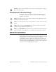
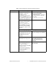
Table 1. NI Driver and Application Software Documentation Software NI-DAQmx for Windows Document/Description Location/Topic DAQ Getting Started Guide—describes how to install and use the NI-DAQmx driver software for Windows and your data acquisition (DAQ) device, how to confirm the device is operating properly, and how to take an NI-DAQmx measurement. Start»Programs»National Instruments»NI-DAQ» DAQ Getting Started Guide NI-DAQ Readme—includes information about NI-DAQmx.
Table 1. NI Driver and Application Software Documentation (Continued) Software LabVIEW Document/Description Location/Topic Getting Started with LabVIEW—describes the LabVIEW graphical programming environment and the basic LabVIEW features you use to build data acquisition and instrument control application.
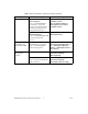
Table 1. NI Driver and Application Software Documentation (Continued) Software LabWindows™/CVI™ Document/Description Location/Topic LabWindows/CVI Help Data Acquisition book—contains NI-DAQmx measurement concepts and step-by-step instructions about creating a measurement task using the DAQ Assistant.
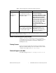
Table 1. NI Driver and Application Software Documentation (Continued) Software .NET Languages without NI Application Software* Document/Description Location/Topic NI-DAQmx .NET Help—contains conceptual topics for using NI-DAQmx with Visual C# and Visual Basic .NET. Start»All Programs»National Instruments»NI-DAQ» NI-DAQmx .NET Reference Help. Expand NI Measurement Studio Help»NI Measurement Studio .NET Class Library»Reference to view the function reference.
Installing the Software NI WLS/ENET-9000 Series device software support for Windows Vista/XP/2000 is provided by NI-DAQmx. The DAQ Getting Started Guide, which is accessible from Start» Programs»National Instruments»NI-DAQ or at ni.com/manuals, offers NI-DAQmx users step-by-step instructions for installing software and hardware, configuring channels and tasks, and getting started developing an application.
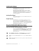
1 2 1 Stacking Grooves (NI ENET-9000 Series Only) 2 Rubber Standoffs Figure 3. Stacking Grooves and Rubber Standoffs for Desktop Use Mounting the NI WLS/ENET-9000 Series Device You can mount the NI WLS/ENET-9000 Series device using a 75 mm DIN-Rail kit or a panel mount kit. For kit accessory ordering information, refer to the accessory section of the NI WLS/ENET-9163 product page at ni.com. Caution Your installation must meet the following requirements: • Allows 25.4 mm (1 in.
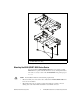
Attaching the NI 9910 DIN-Rail The NI 9910 DIN-Rail kit contains one clip for mounting the device on a standard 35 mm DIN-Rail. To mount the device on a DIN-Rail, fasten the DIN-Rail clip to the device using a number 2 Phillips screwdriver and four M4 × 17 screws. The screws are included in the DIN-Rail kit. Make sure the DIN-Rail kit is installed as illustrated in Figure 4, with the larger lip of the DIN-RAIL positioned up.
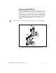
Mounting the NI WLS/ENET-9000 Series to a Panel Thread inserts are located in the NI WLS/ENET-9000 Series device for mounting it to a panel. Refer to Figure 5 for dimensions. 6.500 in. (165.10 mm) Figure 5. Device Panel Mounting Dimensions Remove the C Series I/O module from the NI WLS/ENET-9163 carrier before you mount the carrier to the panel. After the NI WLS/ENET-9163 carrier is mounted, you can reinsert the C Series module.
Setting Up the NI WLS/ENET-9000 Series Device Complete the following steps to prepare the NI WLS/ENET-9000 Series device for use: 1. Before connecting the hardware, install NI-DAQmx software, LabVIEW SignalExpress, and the NI-DAQ Device Documentation Browser. Refer to the DAQ Getting Started Guide for more information about software installation. The NI-DAQmx software is included on the CD shipped with your kit and is available for download at ni.com/support.
1 K LIN R WLS RO ER US STATR PW PR1 GND SET PR0 C V GND er RE 163 Carri S-9 ies WL Ser NI2.11g C 80 00 10/1 V 9-30 UT X INP W MA /ACT 4.5 LINK 1 Ring Lug Attached to the Ground Screw Figure 6. Ring Lug Attached to the Ground Screw Note Additionally, attach a wire with a ring lug to all other C Series I/O module cable shields. You must connect this wire to the ground terminal of the device using the ground screw.
Device Interface Figure 7 shows the NI WLS/ENET-9163 carrier interface. 1 V 2 WLS LINK ACTIVE STATUS POWER GND PFI1 C 3 RESET PFI0 INPUT 9-30 V 4.5 W MAX GND LINK/ACT 6 7 1 2 3 RJ-45 Ethernet Port LEDs: WLS LINK*, ACTIVE, STATUS, and POWER Reset Button 5 NI WLS-9163 802.11g C Series Carrier 10/100 4 4 5 6 7 Trigger Connector 10/100 LED LINK/ACT LED Power Connector * NI WLS-9163 Carrier Only. Figure 7.
LED Indicators The LED indicators for the NI WLS/ENET-9000 Series device are listed in Table 2. Table 2.
Pinouts Trigger Connector GND PFI 1 GND PFI 0 Figure 8. Trigger Connector Pinout Cabling Table 3 shows the standard Ethernet cable wiring connections for both normal and crossover cables. Table 3.
Connector 1 Pin 1 Connector 2 Pin 8 Pin 1 Pin 8 Figure 9. Ethernet Connector Pinout Using the NI WLS/ENET-9000 Series Device C Series I/0 Modules National Instruments C Series I/O modules provide built-in signal conditioning and screw terminal, spring terminal, BNC, D-SUB, or RJ-50 connectors. A wide variety of I/O types are available, allowing you to customize the your system to meet your application needs. You can swap C Series modules when the NI WLS/ENET-9163 carrier is plugged in.
Analog Input To perform analog input measurements, insert a supported analog input C Series I/O module into the NI WLS/ENET-9163 carrier. The measurement specifications, such as number of channels, channel configuration, sample rate, and gain, are determined by the type of C Series I/O module used. For more information and wiring diagrams, refer to the documentation included with your C Series I/O modules.
The NI-DAQmx Help is available after installation from Start» Programs» National Instruments»NI-DAQ»NI-DAQmx Help. To view the LabVIEW Help, in version 8.0 or later, select Help»Search the LabVIEW Help in LabVIEW. Alternately, to download the LabVIEW Help, go to ni.com/manuals. You also can specify whether the measurement acquisition begins on the rising edge or falling edge of ai/StartTrigger. Routing AI Start Trigger to an Output Terminal You can route ai/StartTrigger to the PFI 0 terminal.
When the reference trigger occurs, the NI WLS/NET-9163 Series device continues to write samples to the buffer until the buffer contains the number of posttrigger samples desired. Figure 10 shows the final buffer. Reference Trigger Pretrigger Samples Posttrigger Samples Complete Buffer Figure 10. Reference Trigger Final Buffer Using a Digital Source To use ai/ReferenceTrigger with a digital source, specify a source and an edge. PFI 0 can provide the source.
Note Pause triggers are only sensitive to the level of the source, not the edge. Analog Input Timing Signal AI Sample Clock A sample consists of one reading from each channel in the AI task. ai/SampleClock signals the start of a sample of all analog input channels in the task. ai/SampleClock can be generated from external or internal sources. Using A Digital Source To use ai/SampleClock, specify a source and an edge on PFI 1.
Simultaneous Sample-and-Hold Simultaneous sample-and-hold (SSH) C Series analog input modules contain multiple A/D converters or circuitry that allows all the input channels to be sampled at the same time. These modules sample their inputs on every AI Sample Clock pulse. Sigma-Delta Sigma-Delta C Series analog input modules function much like SSH modules, but use A/D converters that require a high-frequency oversample clock to produce accurate, synchronized data.
Specifications These specifications are typical at 25 °C unless otherwise noted. For C Series I/O module specifications, refer to the documentation included with the modules. Note These specifications are for the NI WLS/ENET-9163 carrier only, unless otherwise noted. Analog Input Input FIFO size ...................................... 4095 samples >16 bit 8191 samples ≤16 bit Sample rate1 NI WLS/ENET-9163 carrier........... 5 MS/s (multi-channel, aggregate), maximum With NI WLS/ENET-9215 .............
PFI Functionality PFI 1 .......................................................Sample Clock In, Sample Clock Out1 PFI 0 .......................................................Start Trigger In, Start Trigger Out, Pause In, Reference Trigger In Maximum Operation Conditions Level Min Max IOL output low current — 8 mA IOH output high current — –8 mA Digital Input Characteristics Level Min Max VIL input low voltage 0V 0.
Security ...................................................WEP-40, WEP-104, WPA, WPA2 EAP Type .................................LEAP, PEAP1, TTLS2, TLS Center frequency 11b ...................................................2412–2484 MHz 11g ...................................................2412–2472 MHz Channel interval 11b ...................................................5 MHz 11g ...................................................5 MHz Modulation type 11g .............................................
11g, PER<10% 54 Mbps ...........................................–68 dB/min 48 Mbps ...........................................–68 dB/min 36 Mbps ...........................................–75 dB/min 24 Mbps ...........................................–79 dB/min 18 Mbps ...........................................–82 dB/min 12 Mbps ...........................................–84 dB/min 9 Mbps .............................................–87 dB/min 6 Mbps .............................................
Module I/O States At power-on ........................................... Module-dependent. Refer to the documentation included with the C Series I/O module. Power Requirements Caution You must use a National Electric Code (NEC) UL Listed Class 2 power supply with NI WLS/ENET-9000 Series devices. Some C Series I/O modules have additional power requirements. For more information about the C Series I/O module power requirements, refer to the documentation included with the C Series I/O module.
Safety Standards If you need to clean the carrier, wipe it with a dry towel. The NI WLS/ENET-9163 carrier is designed to meet the requirements of the following standards of safety for electrical equipment for measurement, control, and laboratory use: • IEC 61010-1, EN 61010-1 • UL 61010-1, CSA 61010-1 • EN 503711 Note For UL and other safety certifications, refer to the product label, or go to ni.
Environmental The NI WLS/ENET-9163 carrier is intended for indoor use only. For outdoor use, mount the system in a suitably rated enclosure. Operating temperature (IEC-60068-2-1 and IEC-60068-2-2) .... 0 to 55 °C Storage temperature (IEC-60068-2-1 and IEC-60068-2-2) .... –10 to 70 °C Ingress protection ................................... IP 30 Operating humidity (IEC-60068-2-56)................................... 10 to 90% RH, noncondensing Storage humidity (IEC-60068-2-56) ......
Electromagnetic Compatibility This product is designed to meet the requirements of the following standards of EMC for electrical equipment for measurement, control, and laboratory use: • EN 61326 EMC requirements; Minimum Immunity • EN 55011 Emissions; Group 1, Class A • CE, C-Tick, ICES, and FCC Part 15 Emissions; Class A • EN 301489-011, EN 301489-171 • FCC 15-2471, IC RSS-2101, EN 3003281 Note For EMC compliance, operate this device according to product documentation.
• Plug the transmitter into a different outlet so that the transmitter and the receiver are on different branch circuits. This hardware may generate emissions that exceed regulatory requirements or may become more sensitive to disturbances in the local electromagnetic environment when test leads are attached or when connected to a test object. Operation of this hardware in a residential area is likely to cause harmful interference.
Ελληνική [Greek] ΜΕ ΤΗΝ ΠΑΡΟΥΣΑ National Instruments ΔΗΛΩΝΕΙ ΟΤΙ NI WLS/ENET-9163 ΣΥΜΜΟΡΦΩΝΕΤΑΙ ΠΡΟΣ ΤΙΣ ΟΥΣΙΩΔΕΙΣ ΑΠΑΙΤΗΣΕΙΣ ΚΑΙ ΤΙΣ ΛΟΙΠΕΣ ΣΧΕΤΙΚΕΣ ΔΙΑΤΑΞΕΙΣ ΤΗΣ ΟΔΗΓΙΑΣ 1999/5/ΕΚ. Français [French] Par la présente National Instruments déclare que l'appareil NI WLS/ENET-9163 est conforme aux exigences essentielles et aux autres dispositions pertinentes de la directive 1999/5/CE.
Environmental Management National Instruments is committed to designing and manufacturing products in an environmentally responsible manner. NI recognizes that eliminating certain hazardous substances from our products is beneficial not only to the environment but also to NI customers. For additional environmental information, refer to the NI and the Environment Web page at ni.com/environment.
Regulatory Information1 United States This product generates and radiates radio frequency energy. To comply with the radio frequency radiation exposure guidelines in an uncontrolled environment, this equipment must be installed and operated while maintaining a minimum body-to-antenna distance of 20 cm. This product complies with Part 15 of the FCC Rules.
Europe – Restrictions for Use of 2.4 GHz Frequencies in European Community Countries België/ Belgique: For private usage outside buildings across public grounds over less than 300m no special registration with IBPT/BIPT is required. Registration to IBPT/BIPT is required for private usage outside buildings across public grounds over more than 300m. For registration and license please contact IBPT/BIPT.
Where to Go for Support National Instruments corporate headquarters is located at 11500 North Mopac Expressway, Austin, Texas, 78759-3504. National Instruments also has offices located around the world to help address your support needs. For telephone support in the United States, create your service request at ni.com/support and follow the calling instructions or dial 512 795 8248.