NI Vision NI 17xx Smart Camera User Manual NI 17xx Smart Camera User Manual June 2008 372429B-01
Support Worldwide Technical Support and Product Information ni.
Important Information Warranty NI 17xx Smart Cameras are warranted against defects in materials and workmanship for a period of one year from the date of shipment, as evidenced by receipts or other documentation. National Instruments will, at its option, repair or replace equipment that proves to be defective during the warranty period. This warranty includes parts and labor.
Compliance Compliance with FCC/Canada Radio Frequency Interference Regulations Determining FCC Class The Federal Communications Commission (FCC) has rules to protect wireless communications from interference. The FCC places digital electronics into two classes. These classes are known as Class A (for use in industrial-commercial locations only) or Class B (for use in residential or commercial locations). All National Instruments (NI) products are FCC Class A products.
Contents About This Manual Conventions ...................................................................................................................ix Related Documentation..................................................................................................x Hardware Documents ......................................................................................x NI Vision Builder for Automated Inspection Documents...............................
Contents Chapter 4 Lighting Lighting Connector........................................................................................................ 4-1 Direct Drive Lighting Controller................................................................................... 4-2 Lighting Files .................................................................................................. 4-4 Selecting a Light .............................................................................................
Contents Chapter 7 Ethernet Ports Ethernet LEDs................................................................................................................7-2 ACTIVITY/LINK LED...................................................................................7-2 SPEED LED ....................................................................................................7-2 DHCP and Static IP Address Assignment .....................................................................
About This Manual This manual describes the electrical and mechanical aspects of the National Instruments 17xx Smart Camera. Refer to Getting Started with the NI 17xx Smart Camera for smart camera and accessory installation information. Conventions The following conventions appear in this manual: » The » symbol leads you through nested menu items and dialog box options to a final action.
About This Manual Related Documentation The following documents contain information that you may find helpful as you read this manual: Hardware Documents • Getting Started with the NI 17xx Smart Camera—Contains important safety information and information about installing and configuring NI Smart Cameras and accessories. You can access this manual by navigating to Start»All Programs»National Instruments»Vision» Documentation»NI-IMAQ.
About This Manual LabVIEW and NI Vision Development Module Documents • LabVIEW Help—Includes information about LabVIEW programming concepts, step-by-step instructions for using LabVIEW, and reference information about LabVIEW VIs, functions, palettes, menus, and tools. • Getting Started with LabVIEW—Use this manual as a tutorial to familiarize yourself with the LabVIEW graphical programming environment and the basic LabVIEW features you use to build data acquisition and instrument control applications.
1 NI Smart Camera Overview This chapter provides an overview of the features and components of the National Instruments Smart Camera. Refer to Getting Started with the NI 17xx Smart Camera for smart camera and accessory installation information. Hardware Overview The NI Smart Camera is available in several different configurations. When a feature pertains only to specific smart camera models, a list at the beginning of the section shows which smart camera models support the feature.
Chapter 1 NI Smart Camera Overview For more information about the image sensors, refer to Chapter 3, NI Smart Camera Image Sensor. For complete smart camera specifications, refer to Appendix A, Specifications. All smart cameras have an RS-232 serial port, Gigabit Ethernet ports, and use a standard C-mount lens. Some smart camera models also include the Direct Drive lighting controller and support for quadrature encoders.
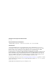
Chapter 1 NI Smart Camera Overview Figure 1-1 shows the smart camera. 4 1 2 7 + 3 GND 5V 24V 5 NI 17XX SMART CAMERA 1 2 3 4 Image Sensor Standard C Lens Mount Lighting Connector LEDs 5 6 7 6 DIP Switches POWER-I/O Connector Ethernet Ports Figure 1-1.
Chapter 1 NI Smart Camera Overview Software Overview Developing applications with the NI Smart Camera requires one of the following software options: Vision Builder for Automated Inspection or LabVIEW LabVIEW Real-Time Module NI Vision Development Module NI Vision Acquisition Software The installation and configuration process for each development environment is different. Refer to Getting Started with the NI 17xx Smart Camera for installation and configuration instructions.
Chapter 1 NI Smart Camera Overview LabVIEW LabVIEW is a graphical programming environment for developing flexible and scalable applications. To develop machine vision applications with the NI Smart Camera and LabVIEW, you must have the following add-on modules: LabVIEW Real-Time Module, NI Vision Development Module, and Vision Acquisition Software.
Chapter 1 NI Smart Camera Overview NI Vision Acquisition Software The NI Vision Acquisition Software CD contains Measurement & Automation Explorer (MAX) configuration software and NI-IMAQ driver software. Use MAX to configure the NI Smart Camera. You can set the IP address, update software on the smart camera, configure triggering, and set up the lighting features.
2 Power and I/O This chapter provides information about the NI Smart Camera POWER-I/O connector, connecting isolated inputs and isolated outputs, and connecting to serial devices and to quadrature encoders. POWER-I/O Connector The POWER-I/O connector provides signal connections for power and I/O, including isolated inputs and outputs, quadrature encoders, and serial devices. The POWER-I/O connector is a standard female high-density 15-pin D-SUB connector.
Chapter 2 Power and I/O Table 2-1.
Chapter 2 Power and I/O If you are using the Direct Drive lighting controller, the power supply wattage must be sufficient to power both the camera and the light. The power required by the light can be significantly more than the power required by the smart camera. Isolated Inputs Caution Do not apply a voltage greater than 30 VDC to the isolated inputs. Voltages greater than 30 VDC may damage the NI Smart Camera.
Chapter 2 Power and I/O Sensor Power TrigIn+ IsoIn(0)+ NPN (Sinking) Output Device IsoIn(1)+ Sensor Common TrigIn– IsoIn(0)– IsoIn(1)– NI 17xx Figure 2-2. Connecting External Sinking Output Sensors to Isolated Inputs Isolated Outputs Caution Do not power the load connected to the isolated outputs with any external power supply greater than 30 VDC. Voltages greater than 30 VDC may damage the NI Smart Camera.
Chapter 2 Power and I/O The isolated outputs can be used to drive external loads, as shown in Figures 2-3 and 2-4. Sensor Power IsoOut+ Sourcing Load Sensor Common IsoOut– NI 17xx Figure 2-3. Connecting an Isolated Output to a Sourcing External Load IsoOut+ IsoOut– NI 17xx Sensor Power Sinking Load Sensor Common Figure 2-4.
Chapter 2 Power and I/O Protecting Against Inductive Loads When an inductive load, such as a relay or solenoid, is connected to an output, a large counter-electomotive force may occur at switching time due to energy stored in the inductive load. This flyback voltage can damage the outputs and the power supply. To limit flyback voltages at the inductive load, install a flyback diode across the load. Mount the flyback diode as close to the load as possible.
Chapter 2 Power and I/O Connecting to a Quadrature Encoder This section applies only to the following NI Smart Cameras: • NI 1742 • NI 1762 • NI 1744 • NI 1764 Connect RS-422 compatible differential quadrature encoders to the NI 17xx Smart Camera to provide positional information. A quadrature encoder uses two output channels, Phase A and Phase B, to track the position of a rotary shaft. Generally, the shaft is coupled to a motor drive that controls the movement of an object.
Chapter 2 Power and I/O Figure 2-5 shows an example of connecting the quadrature encoder differential line drivers. Encoder NI 17xx Phase A+ Phase A Twisted Pair Phase A– Phase A– Phase B+ Phase B Twisted Pair Phase B– Phase B– Figure 2-5. Connecting Differential Line Drivers Figure 2-6 shows the internal quadrature encoder/RS-422 input circuit. +3.3 V 10 kΩ 10 kΩ 10 kΩ 10 kΩ Phase A+ + Phase A– – Phase B+ + Phase B– – 7.5 kΩ 7.5 kΩ 7.5 kΩ 7.5 kΩ NI 17xx Figure 2-6.
NI Smart Camera Image Sensor 3 This chapter provides an overview of the NI Smart Camera image sensors, field of view, spectral response, partial scan mode, binning, gain, and hardware binarization. NI 1722/1742/1762 Smart Cameras use a VGA sensor. NI 1744/1764 Smart Cameras use an SXGA sensor. Refer to Appendix A, Specifications, for information about your smart camera image sensor. Field of View The field of view is the area under inspection that will be imaged by the NI Smart Camera.
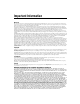
Chapter 3 NI Smart Camera Image Sensor Figure 3-1 illustrates horizontal field of view and working distance. 1 2 3 1 2 Horizontal Imaging Width Working Distance 3 Horizontal Field of View Figure 3-1. Parameters of an Imaging System For example, if the working distance of your imaging setup is 100 mm, and the focal length of the lens is 8 mm, then the field of view in the horizontal direction of a smart camera using the VGA sensor in full scan mode is 0.
Chapter 3 NI Smart Camera Image Sensor Image Sensor Spectral Response The spectral response curve describes the relative sensitivity of the sensor to different wavelengths of light. The peak responsiveness of the VGA and SXGA sensors is to light with a wavelength of approximately 500 nm. If you are imaging a dim scene, this information can be useful when selecting a light source to use in your application as the camera is most sensitive at its peak responsiveness.
Chapter 3 NI Smart Camera Image Sensor Binning Binning can improve the light sensitivity of the sensor by treating adjacent pixels as a single pixel. Binning allows the image sensor to collect more electrons per pixel, which reduces the amount of required light and exposure time. Binning results in higher frame rates and lower spatial resolution in the vertical direction. The NI Smart Camera supports 1 × 2 binning. Figure 3-3 illustrates what happens to the sensor output during binning.
Chapter 3 NI Smart Camera Image Sensor Figure 3-4 shows what happens when gain is applied to a signal. Pixel Value 255 Pixel Value 255 Pixel Value 255 b. a. a Low Gain b Medium Gain c. c High Gain Figure 3-4. Effect of Gain on the Video Signal In Figure 3-4a, low gain has been applied to the signal. The pixel values in the image are grouped close together. In Figure 3-4b, medium gain has been applied to the signal; there are now more notable differences in pixel value within the image.
Chapter 3 NI Smart Camera Image Sensor image pixels to black. Pixels inside the threshold interval are considered part of the particle region. Pixels outside the threshold interval are considered part of the background region. Inverse binarization reverses the assigned bit numbers of the particle region and the background region.
4 Lighting One of the most important aspects of setting up your imaging environment is proper illumination. Images acquired under proper lighting conditions make your image processing software development easier and overall processing time faster. The following sections describe how to use the Direct Drive lighting controller and the strobe outputs of the NI Smart Camera to control a light. Lighting Connector Figure 4-1 shows the lighting connector on the NI Smart Camera.
Chapter 4 Lighting Additional/replacement plugs for use with the lighting connector, part number 780260-01, are available from NI. Note Direct Drive Lighting Controller This section applies only to the following NI Smart Cameras: • NI 1742 • NI 1762 • NI 1744 • NI 1764 The NI Smart Camera offers an innovative lighting controller that directly powers third-party current controlled lights. With other smart cameras, a lighting controller that drives a light must be purchased separately.
Chapter 4 Lighting The smart camera automatically synchronizes the lighting strobe with the image sensor exposure. The smart camera always turns the light on before an exposure starts and turns the light off once the exposure completes. The duration of the light strobe is dictated by the exposure time. Refer to Chapter 5, Image Acquisition, for more information.
Chapter 4 Lighting Lighting Files A lighting file is a text file that contains information about a light, such as the type and color of the light, maximum current limit, and maximum strobe duty cycle. Lighting files have the extension .ild. MAX and Vision Builder AI use lighting files to ensure that the current limits and duty cycle of your light are not exceeded when the light is used with the Direct Drive lighting controller.
Chapter 4 Lighting To use a light that does not have a lighting file, you can enter the lighting data manually in MAX or Vision Builder AI: • In MAX—Select the Lighting tab of the NI Smart Camera configuration page. Click Configure Light, and select Enter Lighting Data Manually. • In Vision Builder AI—Select the Lighting tab of the Acquire Image (Smart Camera) step. Click Configure Light Source, and select Enter Lighting Data Manually.
Chapter 4 Lighting • The minimum voltage drop specified for the light does not fall below the specified range of the smart camera. Under some circumstances some LEDs, particularly certain lights with infrared LEDs and lights with only one LED per string, present a lower voltage drop than usual and may be incompatible with the smart camera. These lights may need to be reconfigured by the manufacturer to bring the voltage drop within the specified range of the smart camera.
Chapter 4 Lighting The Direct Drive controller performs an initialization sequence to achieve the requested current output prior to acquiring the first image. You may notice a sequence of short flashes from the light when the application initializes or shuts down.
Chapter 4 Lighting cycle that do not violate the limits of the external controller and/or light(s). Refer to the Maximum Frame Rate section of Chapter 5, Image Acquisition, for more information. Enable the 5 V and 24 V lighting outputs as follows: • In Vision Builder AI, enable the 5 V TTL Strobe and/or 24 V Strobe controls on the Lighting tab of the Acquire Image (Smart Camera) step.
Chapter 4 Lighting Figure 4-4 illustrates how to connect an external lighting controller to the 24 V output on the NI Smart Camera. 24 V Strobe Output (~ 18 V – 30 V) GND Output External Lighting Controller LED NI 17xx Figure 4-4.
5 Image Acquisition This chapter contains information about acquiring images with the NI Smart Camera and explains the relationships between triggering, lighting, and exposure. Exposure The NI Smart Camera provides control of the image sensor exposure time through software. The exposure time is the amount of time that light is allowed to strike the sensor to produce an image. When light strikes the surface of the sensor, it dislodges electrons.
Chapter 5 Image Acquisition can be used to calculate the maximum exposure. Assuming the object is moving horizontally across the field of view, use Equation 5-1 to calculate the maximum exposure time.
Chapter 5 Image Acquisition In fixed-frame-rate mode, you can specify a frame rate that is less than or equal to the maximum frame rate by setting the Frame Rate property in LabVIEW. Setting the Frame Rate property will implicitly take you out of free-run mode and into fixed-frame-rate mode. To return to free-run mode, set the Fixed-Frame-Rate Mode property in LabVIEW to FALSE. Note Vision Builder AI and MAX do not support fixed-frame-rate mode.
Chapter 5 Image Acquisition Figure 5-1 illustrates the relationship between an external trigger, a lighting strobe, and the exposure time. 1 Trigger Lighting Strobe Exposure Image Readout 3 2 1 2 User-Configurable Trigger Delay Lighting Turn-On Time 3 Beginning of Image Readout Figure 5-1. Externally Triggered Mode The trigger shown in Figure 5-1 represents an external trigger, configured to use the rising edge as the active edge.
Chapter 5 Image Acquisition The incoming trigger is synchronized to the line rate of the smart camera. This adds an additional delay that can vary on a frame by frame basis. The maximum variability is shown in Table 5-1. Table 5-1. Trigger Synchronization Variability Smart Camera Model Trigger Synchronization Variability NI 1722 NI 1742 NI 1762 31.2 μs NI 1744 NI 1764 71.
Chapter 5 Image Acquisition end of the exposure pulse. The end of an exposure starts the image readout from the sensor. The maximum trigger rate is determined by the maximum frame rate for your configuration. Refer to the Maximum Frame Rate section for information about the factors that affect the maximum frame rate. Maximum Frame Rate Frame rate is the inverse of the frame period.
Chapter 5 Image Acquisition Determining the Maximum Frame Rate You can determine the maximum frame rate for your configuration in software by reading the Max Frame Rate indicator in Vision Builder AI, reading the Max Frame Rate property in LabVIEW, or reading the Max Frame Rate indicator in MAX. When external triggering is enabled, do not trigger faster than the maximum frame rate. Note Sending a trigger faster than the maximum frame rate will result in a missed trigger.
Chapter 5 Image Acquisition Determining the Exposure Time The minimum frame period depends on exposure time, lighting mode, and trigger delay. A longer exposure time results in a longer frame period, and a slower maximum frame rate. Determining the Lighting Mode If you are not strobing a light using the Direct Drive or the external strobe outputs of the smart camera, the smart camera can expose one image while it is reading out the previous image, allowing for the highest possible frame rates.
Chapter 5 Image Acquisition When strobing is enabled, the smart camera waits until the image readout is complete before turning on the light for the next frame, as shown in Figure 5-4. 1 Trigger Lighting Strobe Exposure Image Readout 1 Image Readout Completes Before Lighting Strobe Asserts for Next Image Figure 5-4.
Chapter 5 Image Acquisition Refer to Equations 5-5 and 5-6 to calculate the minimum frame period for triggered acquisitions with and without strobing. min frame period NoStrobeWithTrigger = max ( T + L + E, Trigger Delay ) (5-5) min frame period WithStrobeWithTrigger = max ( T + L + E + R, Trigger Delay ) (5-6) where T is the trigger synchronization variability, L is the lighting turn-on time, E is the exposure time, and R is the image readout duration.
6 LEDs and DIP Switches This chapter provides information about the location and functionality of the LED indicators and DIP switches on the NI Smart Camera. Understanding the LED Indicators Figure 6-1 shows the location of the LEDs on the NI Smart Camera. FAIL PASS IMG ACQ STATUS POWER Figure 6-1.
Chapter 6 LEDs and DIP Switches Device Initialization While the NI Smart Camera initializes, the POWER LED lights solid green and the STATUS, IMG ACQ, PASS, and FAIL LEDs exhibit a scrolling pattern. When the smart camera finishes initializing, the STATUS LED lights solid green. If the system does not initialize within the expected period of time, the STATUS LED flashes a status code. Refer to the STATUS LED section for information about the status codes.
Chapter 6 LEDs and DIP Switches Table 6-1. STATUS LED Indications LED Behavior LED Color Solid Green The smart camera initialized successfully and is ready for use. 1 Flash Green The smart camera IP address or software is unconfigured. The smart camera ships from the factory unconfigured. The smart camera also enters the unconfigured state if it is configured for DHCP and no DHCP server is available. Use MAX or Vision Builder AI to configure the smart camera.
Chapter 6 LEDs and DIP Switches IMG ACQ LED The IMG ACQ LED briefly lights green when an image is captured and ready for analysis. Fast frame rates can give this LED the appearance of being continuously lit. If the IMG ACQ LED and the FAIL LED both flash red, it indicates that the NI Smart Camera has shut down because the maximum internal temperature was exceeded.
Chapter 6 LEDs and DIP Switches SAFE MODE Switch ON SAFE MODE IP RESET NO APP CONSOLE To start the NI Smart Camera in safe mode, move the SAFE MODE switch to the ON position and reapply power or restart the smart camera. If the switch is in the ON position when the smart camera starts, the smart camera launches only the essential services required for updating configuration information and installing software. The LabVIEW Real-Time engine does not launch.
Chapter 6 LEDs and DIP Switches NO APP Switch ON SAFE MODE IP RESET NO APP CONSOLE Move the NO APP switch to the ON position to prevent a startup application from running when the NI Smart Camera powers on. If you want to permanently disable the application from running when the smart camera powers on, you can disable the startup application in software. To automatically run an application when the smart camera powers on, keep the NO APP switch in the OFF position.
7 Ethernet Ports This chapter provides information about the Ethernet ports and Ethernet LEDs on the NI Smart Camera and considerations for assigning an IP address. The Ethernet ports on the smart camera provide a connection between the smart camera and the development computer or other network devices. The smart camera provides two 10/100/1,000 Mbps Ethernet ports. Figure 7-2 shows the Ethernet ports on the smart camera. 1 Port 1 1 2 1 2 2 Port 2 Figure 7-1.
Chapter 7 Ethernet Ports A CAT 5e or CAT 6 1000Base-T Ethernet cable is required to achieve maximum 1,000 Mbps (Gigabit) Ethernet performance. CAT 5e and CAT 6 Ethernet cables adhere to higher electrical standards required for Gigabit Ethernet communication. CAT 5 cables are not guaranteed to meet necessary electrical requirements.
Chapter 7 Ethernet Ports Table 7-1. SPEED LED Behavior SPEED LED Behavior Off Indication No link or a 10 Mbps link is negotiated Solid Green A 100 Mbps link is negotiated Solid Amber A 1,000 Mbps link is negotiated DHCP and Static IP Address Assignment You must configure the IP settings for the NI Smart Camera prior to use. You can assign a static IP address or, if your network has a DHCP server, you can use a DHCP server to assign an IP address.
Chapter 7 Ethernet Ports to the DHCP server, the smart camera does not appear in MAX or Vision Builder AI. The IP address must to be reconfigured before you can use the smart camera. Firewall Considerations If you are having difficulty detecting the system and setting up the NI Smart Camera on your network, you must configure the firewall to open the TCP/UDP ports used by the smart camera and the host machine. The smart camera uses the ports listed in Table 7-2. Table 7-2.
8 Thermal Considerations and Mounting This chapter contains information about the operating temperature of the NI Smart Camera and provides the information necessary to create a custom mount for the smart camera. Thermal Considerations The NI Smart Camera can operate in environments with ambient temperatures ranging from 0 to 45 °C. The maximum housing temperature of the smart camera is 65 °C. Refer to Appendix A, Specifications, for complete specifications.
Chapter 8 Thermal Considerations and Mounting Operating the smart camera above the specified ambient temperature or above the specified case temperature will degrade image quality and can cause permanent damage to the device. The smart camera also has a internal temperature sensor that provides an internal temperature measurement. You can monitor the temperature sensor from LabVIEW using the Status Information»Temperature property from the IMAQ property node.
Chapter 8 Thermal Considerations and Mounting Figures 8-2 through 8-5 provide the dimensional drawings necessary to create a custom mount for the smart camera. 95.75 mm (3.770 in.) 47.00 mm (1.850 in.) 60.58 mm 85.80 mm (2.385 in.) (3.378 in.) 23.50 mm (0.925 in.) Optical Axis 24.25 mm (0.955 in.) Optical Axis Figure 8-2. Back View of the NI Smart Camera with Dimensions 30.89 mm (1.216 in.) 32.80 mm (1.291 in.) 38.91 mm (1.532 in.) Figure 8-3.
Chapter 8 Thermal Considerations and Mounting 117.66 mm (4.632 in.) 44.14 mm (1.738 in.) 50.62 mm (1.993 in.) Figure 8-4. Side View of the NI Smart Camera with Dimensions 33.12 mm (1.304 in.) 20.71 mm (0.815 in.) 21.41 mm (0.843 in.) 24.78 mm (0.975 in.) 25.45 mm (1.002 in.) Optical Axis 27.86 mm (1.097 in.) 13.84 mm (0.545 in.) Figure 8-5. Bottom View of the NI Smart Camera with Dimensions NI 17xx Smart Camera User Manual 8-4 ni.
A Specifications The following specifications apply to the NI 1722/1742/1744/1762/1764 Smart Camera. These specifications are typical at 25 °C, unless otherwise stated. Power Requirements Power consumption NI 1722 ........................................... 24 VDC, +20%/–15% (IEC 1311); 450 mA NI 1742/1744/1762/1764 Direct Drive disabled............... 24 VDC, +20%/–15% (IEC 1311); 450 mA Direct Drive enabled................ 24 VDC, +20%/–15% (IEC 1311); 800 mA Reverse polarity protection ...............
Appendix A Specifications VGA Sensor (NI 1722/1742/1762 Only) Sensor .....................................................Sony CCD ICX424AL Active pixels (VGA) Full scan...........................................640 × 480 1/2 scan............................................640 × 240 1/4 scan............................................640 × 120 Binning (1 × 2) ................................640 × 240 Pixel size.................................................7.4 μm × 7.
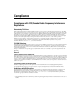
Appendix A Specifications Spectral characteristics........................... Refer to Figure A-1 1.0 0.9 Relative Response 0.8 0.7 0.6 0.5 0.4 0.3 0.2 0.1 0 400 500 600 700 800 900 1000 Wavelength (nm) Figure A-1. VGA Sensor Spectral Response Curve Gamma ................................................... 1.0 fixed SXGA Sensor (NI 1744/1764 Only) Sensor..................................................... Sony CCD ICX205AL Active pixels (SXGA) Full scan ......................................
Appendix A Specifications Maximum frame rate1 Full scan...........................................Up to 13 fps 1/2 scan............................................Up to 23 fps 1/4 scan............................................Up to 39 fps Binning (1 × 2) ................................Up to 26 fps Optical format.........................................1/2 in. Sensor readout ........................................Progressive scan Bits per pixel...........................................
Appendix A Specifications Lighting Direct Drive lighting controller (NI 1742/1744/1762/1764 Only) Maximum current ........................... 500 mA continuous; 1 A strobed Minimum current ............................ 50 mA Light requirements Maximum voltage drop across LED+/LED– terminals ............ 30 V, with ±10% input power supply 25 V, with +20%/–15% input power supply Minimum voltage drop across LED+/LED– terminals ............ 7 V Strobe frequency .............................
Appendix A Specifications Speed ......................................................10; 100; 1,000 Mbps Duplex ....................................................Full, half Speed autodetection ................................Yes Duplex autodetection ..............................Yes Auto MDI/MDI-X correction .................Yes DHCP Support ........................................Port 1 only Serial Baud rates ...............................................Up to 230.4 Kbps Default baud rate ..........
Appendix A Specifications External load power supply range.......... 19 V to 30 V Output current ........................................ 100 mA, maximum per channel Quadrature Encoder (NI 1742/1744/1762/1764 Only) Encoder type .......................................... Differential, RS-422; phase A/phase B, no index Physical Characteristics Lens mount............................................. C-mount Camera housing...................................... Painted die-cast aluminium Dimensions..........
Appendix A Specifications Safety The NI Smart Camera meets the requirements of the following standards for safety and electrical equipment for measurement, control, and laboratory use: • IEC 61010-1, EN 61010-1 • UL 61010-1, CSA 61010-1 Note For UL and other safety certifications, refer to the product label or visit ni.com/ certification, search by model number or product line, and click the appropriate link in the Certification column.
Appendix A Specifications Environmental Management National Instruments is committed to designing and manufacturing products in an environmentally responsible manner. NI recognizes that eliminating certain hazardous substances from our products is beneficial not only to the environment but also to NI customers. For additional environmental information, refer to the NI and the Environment Web page at ni.com/environment.
B Troubleshooting This appendix provides instructions for troubleshooting the NI Smart Camera. Configuration Problems The NI Smart Camera Does Not Appear in MAX or Vision Builder AI Possible causes and solutions: • The smart camera may not be powered. Verify that there is power to the smart camera and that both the smart camera and the development computer are properly connected to the network.
Appendix B Troubleshooting • The cable you are using may be inappropriate for the speed of your network, causing network communication dropout. While 1,000 Mbps communication over short cables lengths can be achieved with the CAT5 cable commonly used for 10 and 100 Mbps, CAT5e and CAT6 cables are more reliable and recommended for 1,000 Mbps links.
Appendix B Troubleshooting NI 17xx Smart Camera for information about installing software on the smart camera or contact National Instruments for assistance. • In the event that the Direct Drive lighting controller detects an abnormal load condition, such as a short circuit on the LED+ output, the smart camera stops image acquisition and returns an error. The Direct Drive stops providing current to the light, and the smart camera may restart.
Appendix B Troubleshooting 2. Measure the smart camera housing temperature at the location indicated in Figure 8-1, Measuring the NI Smart Camera Housing Temperature, and verify that it is within specifications. You must remove power, bring the temperature within specifications, and reapply power to the smart camera to recover from this condition.
Appendix B Troubleshooting may restart. Ensure that your lighting wire connections are correct and/or reconfigure your lighting settings in MAX or Vision Builder AI. • You have requested an amount of current within the specified range of the smart camera and within the maximum lighting current settings you configured in MAX or Vision Builder AI.
Appendix B Troubleshooting • Make sure that you have enabled the corresponding external lighting strobe in MAX or Vision Builder AI. Complete one of the following procedures to enable the correct lighting strobe. MAX 1. Launch MAX. 2. In the Configuration tree, expand Devices and Interfaces. 3. Expand NI-IMAQ Devices. 4. Expand the smart camera you are using. 5. Select the channel you are using. 6. Select the Lighting tab. 7.
Appendix B • Troubleshooting You configured the device in MAX or Vision Builder AI to expect a trigger. Refer to the External Trigger section of Chapter 5, Image Acquisition, for information about configuring an external trigger. LED Error Indications STATUS LED Error Conditions The NI Smart Camera indicates specific error conditions by flashing the STATUS LED a specific number of times.
C Maintenance Do not touch the CCD sensor by hand or with other objects. The sensor can be damaged by electrostatic discharge (ESD), body oils, and particulate matter. Use a lens mount cover whenever a lens is not mounted on the camera to protect the sensor from dust and dirt. Avoid drastic temperature changes to prevent dew condensation. When necessary, use the following procedure to clean the sensor at a workstation equipped with anti-ESD facilities.
Technical Support and Professional Services D Visit the following sections of the award-winning National Instruments Web site at ni.com for technical support and professional services: • Support—Technical support resources at ni.com/support include the following: – Self-Help Technical Resources—For answers and solutions, visit ni.
Appendix D Technical Support and Professional Services • Declaration of Conformity (DoC)—A DoC is our claim of compliance with the Council of the European Communities using the manufacturer’s declaration of conformity. This system affords the user protection for electromagnetic compatibility (EMC) and product safety. You can obtain the DoC for your product by visiting ni.com/certification. If you searched ni.
Glossary Symbol Prefix Value p pico 10 –12 n nano 10 –9 μ micro 10 – 6 m milli 10 –3 k kilo 10 3 M mega 10 6 G giga 10 9 B binary image An image in which the pixels have only one of two intensity values. Objects in the image usually have a pixel intensity of 1 (or 255), and the background has a pixel intensity of 0. C CCD Charge Coupled Device. A chip that converts light into electronic signals. D DIP switch Dual Inline Package switch.
Glossary exposure time The amount of time that light is allowed to strike the imaging sensor to produce an image. F falling edge The digital signal transition from the high state to the low state. field of view The area of inspection that the camera can acquire. fps Frames per second. G gain The amount of increase in signal power, voltage, or current expressed as the ratio of output to input. I IEC International Electrotechnical Commission. A standard-setting body.
Glossary N NI-IMAQ Driver software for National Instruments image acquisition devices and smart cameras. P PLC Programmable Logic Controller. An industrial computer used for factory automation, process control, and manufacturing systems. pulse train A signal consisting of a series of continuous pulses. Q quadrature encoder An encoding technique for a rotating device where two tracks of information are placed on the device, with the signals on the tracks offset by 90 degrees from each other.
Glossary T TCP Transmission Control Protocol. A set of standard protocols for communicating across a single network or interconnected set of networks. TCP is for high-reliability transmissions. trigger Any event that causes or starts some form of data capture. V VDC Volts direct current. VGA sensor Video Graphics Array sensor. Image sensor that features a resolution of 640 × 480 pixels. VI Virtual Instrument.
Index Numerics CONSOLE DIP switch, 6-6 conventions used in the manual, ix 24 V strobe output, 4-7 enabling, 4-8 5 V TTL strobe output, 4-7 enabling, 4-8 D Declaration of Conformity (NI resources), D-2 detailed specifications, A-1 device initialization, 6-2 diagnostic tools (NI resources), D-1 DIP switches, 6-1 Direct Drive, 4-2 connecting a light, 4-6 lighting files, 4-4 selecting a light, 4-5 documentation conventions used in manual, ix NI resources, D-1 related documentation, x drivers (NI resources),
Index G lighting, 4-1 connector, 4-1 controller, 4-2 files, 4-4 turn-on time, 5-5 LUT (lookup table) See hardware binarization gain, 3-4 H hardware binarization, 3-5 help, technical support, D-1 N I National Instruments support and services, D-1 NI 17xx acquiring images, 5-2 assigning an IP address, 7-3 binning, 3-4 communicating with the console, 2-6 connecting an external lighting controller, 4-7 an isolated output to a sinking external load, 2-5 an isolated output to a sourcing external load, 2-5 s
Index Q isolated inputs, 2-3 outputs, 2-4 LEDs, 6-1 lighting, 4-1 connector, 4-1 lighting files, 4-4 models, 1-1 overview, 1-1 partial scan mode, 3-3 power requirements, 2-2 protecting against inductive loads, 2-6 selecting a light, 4-5 software overview, 1-4 specifications, A-1 subnet considerations, 7-4 thermal considerations, 8-1 troubleshooting, B-1 NI support and services, D-1 NI Vision Acquisition Software, 1-6 documents, xi NI Vision Builder for Automated Inspection, 1-4 documents, x NI Vision Deve
Index V troubleshooting, B-1 configuration problems, B-1 firewall problems, B-1 LED error indications, B-7 lighting problems, B-4 network problems, B-1 NI resources, D-1 run-time problems, B-3 triggering problems, B-6 VGA sensor, 3-1 Vision Acquisition Software, 1-6 Vision Builder for Automated Inspection, 1-4 Vision Development Module, 1-5 description, 1-5 W Web resources, D-1 U understanding LED indicators, 6-1 NI 17xx Smart Camera User Manual I-4 ni.