
Universal Analog Input Module User Guide and Specifications

NI USB-9219 User Guide and Specifications 10 ni.com
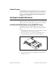
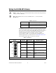
Wiring the NI USB-9219 Device
Caution A high voltage screw terminal backshell must be installed when using hazardous
voltages (>42.4 V
pk
, 60 VDC).
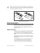
Note Table 2 illustrates the accessories available from ni.com for use with the
NI USB-9219.
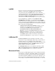
The NI USB-9219 has four 6-terminal connectors that provide connections
for four analog input channels. Connect the positive signal of the signal
source to the positive input signal terminal (HI) and the negative signal of
the signal source to the negative input signal terminal (LO). Use the
excitation terminals if your sensor requires a separate excitation
connection. Refer to Table 3 for the signal names and Table 4 for the
terminal assignments for each mode. Refer to the NI USB-9219 Circuitry
section for information about connections in each mode.
Table 2. Accessories
Accessory Accessory Description
NI 9972 Strain relief for 6-position spring terminal
NI 9973 6-position connectors
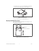
Table 3. Signal Names
Module Terminal Signal Name Signal Description
1 T+ TEDS Data
2 T– TEDS COM
3 EX+/HI
*
Positive excitation or input
signal
4 HI Positive input signal
5 EX–/LO
*
Negative excitation or input
signal
6 LO Negative input signal
*
Depending on the mode, terminals 3 and 5 are either the excitation signals or the input signals.
1
2
3
4
5
6
1
2
3
4
5
6
1
2
3
4
5
6
1
2
3
4
5
6
Ch 0
Ch 1
Ch 2
Ch 3