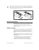
USER GUIDE AND SPECIFICATIONS NI USB-9219 4-Channel, 24-Bit, Universal Analog Input Module This user guide describes how to use the National Instruments USB-9219 and lists the device specifications. Introduction The NI USB-9219 provides a USB interface for four channels of universal analog input with integrated signal conditioning. The NI USB-9219 consists of two components: an NI 9219 module, and an NI USB-9162 carrier, as shown in Figure 1.
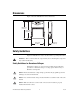
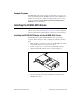
Dimensions Figure 2 shows the NI USB-9219 device dimensions. Hi-Speed USB Carrier NI USB-9162 120.68 mm (4.751 in.) 118.26 mm (4.656 in.) 88.12 mm (3.469 in.) 25.34 mm (0.998 in.) Figure 2. NI USB-9219 Device in Millimeters (Inches) Safety Guidelines Operate the NI USB-9219 only as described in these operating instructions. Hot Surface This icon denotes that the component may be hot. Touching this component may result in bodily injury.
When module terminals are hazardous voltage LIVE (>42.4 Vpk/60 VDC), you must ensure that devices and circuits connected to the module are properly insulated from human contact. You must use the NI 9972 connector backshell kit, as illustrated in Figure 3 to ensure that the terminals are not accessible. Caution Figure 3.
LabVIEW If you are a new user, use the Getting Started with LabVIEW manual to familiarize yourself with the LabVIEW graphical programming environment and the basic LabVIEW features you use to build data acquisition and instrument control applications. Open the Getting Started with LabVIEW manual by selecting Start»All Programs»National Instruments»LabVIEW»LabVIEW Manuals or by navigating to the labview\manuals directory and opening LV_Getting_Started.pdf.
can create channels and tasks, and write your own applications in your ADE using the NI-DAQmx API. For help with NI-DAQmx methods and properties, refer to the NI-DAQmx .NET Class Library or the NI-DAQmx Visual C++ Class Library included in the NI Measurement Studio Help. For general help with programming in Measurement Studio, refer to the NI Measurement Studio Help, which is fully integrated with the Microsoft Visual Studio .NET help. To view this help file in Visual Studio.
Library»Using the Measurement Studio .NET Class Libraries to view conceptual topics for using NI-DAQmx with Visual C# and Visual Basic .NET. To get to the same help topics from within Visual Studio, go to Help» Contents. Select Measurement Studio from the Filtered By drop-down list and follow the previous instructions.
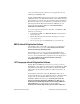
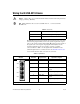
Example Programs The NI-DAQmx CD contains example programs that you can use to get started programming with the NI USB-9219. Refer to the NI-DAQmx for USB Devices Getting Started Guide that shipped with your device, and is also accessible from Start»All Programs»National Instruments» NI-DAQ, for more information. Installing the NI USB-9219 Device Before installing the device, you must install the software you plan to use with the device.
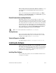
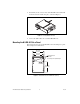
5. Press firmly on the connector side of the NI USB-9219 module until the latches lock the module into place, as shown in Figure 5. Figure 5. Locking Module into Place 6. Connect the USB cable to the assembled NI USB-9219. Mounting the NI USB-9219 to a Panel Threaded inserts are located in the NI USB-9219 for mounting it to a panel. Refer to Figure 6 for dimensions. 85.7 mm (3.37 in.) 72.2 mm (2.84 in.) Threaded Insert M3 x 0.5 8.5 mm (0.34 in.) Max Depth 76.1 mm (3.00 in.) Figure 6.
Connecting the NI USB-9219 to a Computer Plug one end of the USB cable into the NI USB-9219 and the other end into an available USB port on the computer. Refer to the NI-DAQmx for USB Devices Getting Started Guide that shipped with your device, and is also accessible from Start»All Programs»National Instruments»NI-DAQ, for more information. LED Indicator The NI USB-9219 device has a green LED next to the USB connector. The LED indicator indicates device status, as listed in Table 1.
Wiring the NI USB-9219 Device A high voltage screw terminal backshell must be installed when using hazardous voltages (>42.4 Vpk, 60 VDC). Caution Note Table 2 illustrates the accessories available from ni.com for use with the NI USB-9219. Table 2. Accessories Accessory Accessory Description NI 9972 Strain relief for 6-position spring terminal NI 9973 6-position connectors The NI USB-9219 has four 6-terminal connectors that provide connections for four analog input channels.
Table 4.
Wiring TEDS Channels The NI USB-9219 supports only Class II TEDS sensors. Connect the two TEDS lines to TEDS Data (T+) and TEDS COM (T–) and ensure that neither T+ nor T– is tied in common to any of the signal inputs (terminals 3 through 6) on the NI USB-9219. Visit ni.com/info and enter the info code rdteds for information about TEDS sensors. Grounding and Shielding Considerations You can connect ground-referenced or floating signal sources to the NI USB-9219.
NI USB-9219 Timing Options The NI USB-9219 supports four different timing options that are optimized for different types of applications by using different ADC conversion times. High Speed is optimized for high speed at the expense of noise rejection, Best 60 Hz Rejection is optimized for rejection of 60 Hz noise, Best 50 Hz Rejection is optimized for rejection of 50 Hz noise, and High Resolution is optimized for maximum overall noise rejection and provides good rejection of 50 Hz and 60 Hz noise.
4-Wire Resistance and 4-Wire RTD Modes 4-Wire Resistance and 4-Wire RTD modes source a current, which varies based on the resistance of the load, between the EX+ and EX– terminals. The measured resistance is computed from the resulting voltage reading. These modes are not affected by lead wire resistance because a negligible amount of current flows across the HI and LO terminals due to the high input impedance of the ADC. Refer to Figure 12 for an illustration of the connections.
2-Wire Resistance and Quarter-Bridge Modes In 2-Wire Resistance and Quarter-Bridge modes, connect the two ends of the resistor or gauge to the NI USB-9219 across the HI and LO terminals. These modes source a current, which varies based on the resistance of the load, between the HI and LO terminals. The resulting resistance is computed from the voltage measurement. 2-Wire Resistance and Quarter-Bridge modes do not compensate for lead wire resistance. Refer to Figure 14 for an illustration of the connections.
Thermocouple Mode In Thermocouple mode, connect the positive end of the thermocouple to HI and the negative end of the thermocouple to LO. This mode uses the ±125 mV range of the ADC to return a voltage reading. Use shielded cables and twisted-pair wiring and ground the shielded cables. Each channel has a built-in thermistor for cold-junction compensation (CJC) calculations.
Specifications The following specifications are typical for the range 0 to 60 °C unless otherwise noted. Input Characteristics Number of channels ............................... 4 analog input channels ADC resolution ...................................... 24 bits Type of ADC.......................................... Delta-sigma (with analog prefiltering) Sampling mode ...................................... Simultaneous Type of TEDS supported ....................... IEEE 1451.
Overvoltage protection Terminals 1 and 2 ............................±30 V Terminals 3 through 6, across any combination ...................±60 V Input impedance Voltage and Digital In modes (±60 V, ±15 V, ±4 V) ......................1 MΩ Current mode ...................................< 40 Ω All other modes ...............................>1 GΩ Accuracy Gain Error (% of Reading)† Mode, Range Offset Error (ppm of Range)† Voltage, ±60 V ±0.3, ±0.4 ±20, ±50 Voltage, ±15 V ±0.3, ±0.
Stability Gain Drift (ppm of Reading/°C) Mode, Range Offset Drift (ppm of Range/°C) Voltage, ±60 V ±20 ±0.2 Voltage, ±15 V ±20 ±0.8 Voltage, ±4 V ±20 ±3.2 Voltage, ±1 V ±10 ±0.2 Voltage/Thermocouple, ±125 mV ±10 ±1.6 Current, ±25 mA ±15 ±0.
Input noise in ppm of Rangerms Conversion Time High Speed Best 60 Hz Rejection Best 50 Hz Rejection High Resolution Voltage, ±60 V 7.6 1.3 1.3 0.5 Voltage, ±15 V 10.8 1.9 1.9 0.7 Voltage, ±4 V 10.8 2.7 2.7 1.3 Voltage, ±1 V 7.6 1.3 1.3 0.5 Voltage/Thermocouple, 125 mV 10.8 1.9 1.9 1.0 Current, ±25 mA 10.8 1.9 1.9 1.0 4-Wire and 2-Wire Resistance, 10 kΩ 4.1 1.3 0.8 0.3 4-Wire and 2-Wire Resistance, 1 kΩ 7.1 1.8 1.2 0.7 4-Wire and 3-Wire RTD, Pt 1,000 7.6 1.7 1.
Excitation level for Half-Bridge and Full-Bridge modes Mode Load Resistance (Ω) Excitation (V) Half-Bridge 700 2.5 Half-Bridge 240 2.0 Full-Bridge 350 2.7 Full-Bridge 120 2.2 Excitation level for Resistance, RTD, and Quarter-Bridge modes Load Resistance (Ω) Excitation (mV) 120 50 350 150 1,000 430 10,000 2,200 Power Requirements Current consumption from USB ............ 500 mA, max Suspend mode ................................. 2.5 MA, max Bus Interface USB specification ..........
Safety If you need to clean the module, wipe it with a dry towel. Safety Voltages Connect only voltages that are within these limits. Isolation Channel-to-channel Continuous ...............................250 VAC, Measurement Category II Withstand .................................1390 VAC, verified by a 5 s dielectric withstand test Channel-to-earth ground Continuous ...............................250 VAC, Measurement Category II Withstand .................................
Environmental The USB-9219 is intended for indoor use only but may be used outdoors if installed in a suitable enclosure. Operating temperature (IEC 60068-2-1, IEC 60068-2-2)........... 0 to 60 °C Storage temperature (IEC 60068-2-1, IEC 60068-2-2)........... –40 to 85 °C Ingress protection ................................... IP 40 Operating humidity (IEC 60068-2-56) ................................... 10 to 90% RH, noncondensing Storage humidity (IEC 60068-2-56) ...................................
Environmental Management National Instruments is committed to designing and manufacturing products in an environmentally responsible manner. NI recognizes that eliminating certain hazardous substances from our products is beneficial not only to the environment but also to NI customers. For additional environmental information, refer to the NI and the Environment Web page at ni.com/environment.
Where to Go for Support The National Instruments Web site is your complete resource for technical support. At ni.com/support you have access to everything from troubleshooting and application development self-help resources to email and phone assistance from NI Application Engineers. National Instruments corporate headquarters is located at 11500 North Mopac Expressway, Austin, Texas, 78759-3504. National Instruments also has offices located around the world to help address your support needs.