PXI Express NI PXIe-8105 User Manual NI PXIe-8105 User Manual August 2006 371864C-01
Support Worldwide Technical Support and Product Information ni.
Important Information Warranty The NI PXIe-8105 is warranted against defects in materials and workmanship for a period of one year from the date of shipment, as evidenced by receipts or other documentation. National Instruments will, at its option, repair or replace equipment that proves to be defective during the warranty period. This warranty includes parts and labor.
Compliance Compliance with FCC/Canada Radio Frequency Interference Regulations Determining FCC Class The Federal Communications Commission (FCC) has rules to protect wireless communications from interference. The FCC places digital electronics into two classes. These classes are known as Class A (for use in industrial-commercial locations only) or Class B (for use in residential or commercial locations). All National Instruments (NI) products are FCC Class A products.
Contents About This Manual How to Use the Documentation Set...............................................................................ix Conventions ...................................................................................................................ix Related Documentation..................................................................................................x Chapter 1 Introduction Benefits of PXI Express.........................................................................
Contents Installing an ExpressCard ............................................................................... 2-18 Removing an ExpressCard.............................................................................. 2-18 Chapter 3 I/O Information Front Panel Connectors ................................................................................................. 3-1 Front Panel.....................................................................................................................
About This Manual This manual contains detailed instructions for installing and configuring the National Instruments PXIe-8105 embedded computer kit. How to Use the Documentation Set Begin by reading the NI PXIe-8105 Installation Guide, a brief quick-start guide that describes how to install and get started with your controller. This manual, the NI PXIe-8105 User Manual, contains more details about changing the installation or configuration from the defaults and using the hardware.
About This Manual monospace bold Bold text in this font denotes the messages and responses that the computer automatically prints to the screen. This font also emphasizes lines of code that are different from the other examples. Related Documentation The following documents contain information you may find helpful as you read this manual: NI PXIe-8105 User Manual • PICMG EXP.0 R1.0 CompactPCI Express Specification, PCI Industrial Computers Manufacturers Group • IEEE Standard P1284.
1 Introduction This chapter provides overview information for PXI Express and the NI PXIe-8105 embedded controller. Benefits of PXI Express The PXI (PCI eXtensions for Instrumentation) industry standard, an open specification governed by the PXI Systems Alliance (PXISA), has quickly gained adoption and grown in prevalence in test, measurement, and control systems since its release in 1998. One of the key elements driving the rapid adoption of PXI is its use of PCI in the communication backplane.
Chapter 1 Introduction Not only are the trigger bus, 10 MHz system reference clock, and star trigger bus available in PXI retained by PXI Express, but new timing and synchronization features that include a 100 MHz differential system reference clock for the synchronization of multiple modules and three differential star trigger buses for the distribution of precise clock and trigger signals have been added.
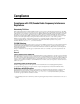
Chapter 1 Core Duo Processor Chipset Graphics Memory Controller Hub x1 PCIE Gigabit Ethernet DVI/VGA DVI-I USB 2.0 x4 USB 2.0 x4 x1 PCIE Express Card/34 Slot GPIB USB SATA Chipset I/O Controller Hub SPI SATA Hard Disk FLASH PCI LPT LPC x4 PCIE GPIB Connector SO-DIMM DDR2 SDRAM PC2 5300 Memory Bus Ch. A/B DMI RJ45 Host Bus Introduction x1 PCIE SMB to PXI Trigger SMB Connector x4 PCIE x4 PCIE COM1 Watchdog PCIE Switch x4 PCIE Super I/O PXI Express PXI Triggers Figure 1-1.
Chapter 1 Introduction • The Watchdog Timer block consists of a watchdog timer that can reset the controller or generate a trigger. • The Chipset ICH7M connects to the PCI, USB, Serial ATA, ExpressCard, PXI Express, and LPC buses. • The USB Connectors connect the chipset to the Hi-Speed USB 2.0 interface. • The Serial ATA Hard Disk is a 60 GB or larger notebook hard disk.1 The Serial ATA interface enables transfer rates up to 1.5 Gb/s. The hard disk also supports Native Command Queuing.
Chapter 1 Introduction specialized functionality. For more information visit ni.com/labview and ni.com/toolkits. If you prefer to use Microsoft’s Visual Basic, Visual C++, and Visual Studio .NET for the core of your application, Measurement Studio adds tools for Measurement and Automation to each language. For more information visit ni.com/mstudio. LabWindows/CVI is an interactive ANSI C programming environment designed for building virtual instrument applications.
Chapter 1 Introduction NI-VISA is the National Instruments implementation of the VISA specification. VISA is a uniform API for communicating and controlling USB, Serial, GPIB, PXI, VXI, and various other types of instruments. This API aids in the creation of portable applications and instrument drivers. For information on writing your own PXI instrument driver with NI-VISA, refer to the NI-VISA Getting Started Manual and the readme.txt file in the NI-VISA directory. For more information visit ni.com/visa.
Installation and Configuration 2 This chapter contains information about installing and configuring your NI PXIe-8105 controller. Installing the NI PXIe-8105 This section contains general installation instructions for the NI PXIe-8105. Consult your PXI Express chassis user manual for specific instructions and warnings. 1. Plug in your chassis before installing the NI PXIe-8105. The power cord grounds the chassis and protects it from electrical damage while you install the module.
Chapter 2 Installation and Configuration 4. Remove the protective plastic covers from the four bracket-retaining screws as shown in Figure 2-1. 1 1 Protective Screw Cap (4X) Figure 2-1. Removing Protective Screw Caps 5. Make sure the injector/ejector handle is in its downward position. Align the NI PXIe-8105 with the card guides on the top and bottom of the system controller slot. Caution Do not raise the injector/ejector handle as you insert the NI PXIe-8105.
Chapter 2 Installation and Configuration 8. Tighten the four bracket-retaining screws on the top and bottom of the front panel to secure the NI PXIe-8105 to the chassis. 9. Check the installation. 10. Connect the keyboard and mouse to the appropriate connectors. If you are using a PS/2 keyboard and a PS/2 mouse, a Y-splitter adapter is available to connect both to a single USB connector. Refer to Figure 4-1, Y-Splitter Cable. 11.
Chapter 2 Installation and Configuration 3. Press the injector/ejector handle down. 4. Slide the unit out of the chassis. BIOS Setup You can change the NI PXIe-8105 configuration settings in the BIOS setup. The BIOS is the low-level interface between the hardware and PC software that configures and tests your hardware when you boot the system. The BIOS setup program includes menus for configuring settings and enabling NI PXIe-8105 controller features.
Chapter 2 Installation and Configuration • —Use this key to return the parent menu of a submenu. At the top-level menus, this key serves as a shortcut to the Exit menu. • <+> and <–>—Use these keys to cycle between all available settings for a selected configuration option. • —Use this key to select time and date fields. Main Setup Menu The most commonly accessed and modified BIOS settings are in the Main setup menu.
Chapter 2 Installation and Configuration Changing settings in this menu may result in an unstable or unbootable controller. If this happens, follow the procedures outlined in the System CMOS section to restore BIOS settings to their factory defaults. Caution The Advanced setup menu includes the following settings: • Reset Configuration Data—A portion of the EEPROM on the controller is designated as the Extended System Configuration Data region (ESCD).
Chapter 2 Installation and Configuration Caution Be careful when choosing the Any OS option for this setting, as instantly removing power from an OS such as Windows can lead to data corruption. Integrated Peripherals Submenu Use this submenu to apply nondefault configurations to the front panel peripherals of an NI PXIe-8105 controller. Normally, you do not need to modify these settings, as the factory default settings provide the most compatible and optimal configuration possible.
Chapter 2 Installation and Configuration function with this option set to either Analog or DVI. The DDC communication path is only enabled when set to Analog for an analog monitor, so certain advanced features of your analog monitor may only be enabled when routing DDC to Analog. The default setting is DVI. Note After changing DDC routing settings, a power cycle is required to enable the change.
Chapter 2 Installation and Configuration only for modern operating systems such as Windows XP or 2000. The default setting is Enabled. Note Refer to KnowledgeBase 3SIC67D8 at ni.com/support for detailed information about switching between APIC and legacy PIC mode for Windows operating systems. • PIRQx Routing—This setting selects the routing option for PXI Express/PCI Express devices connected to PIRQx. This setting affects OSes that do not use APIC routing.
Chapter 2 Installation and Configuration Boot Setup Menu This screen displays the boot order of devices associated with the controller. The BIOS proceeds down the Boot priority order list in search of a bootable device. Devices under the Excluded from boot order list will not be used for booting. If the BIOS fails to find any bootable device, the message Operating System Not Found is displayed, and the system halts. • IDE HDD—The internal hard drive. • USB KEY—A USB based flash disk drive.
Chapter 2 Installation and Configuration • Discard Changes—Any changes made to BIOS settings during this session of the BIOS setup program are discarded. Unlike Exit Discarding Changes, however, the BIOS setup continues to be active. • Save Changes—Changes made to BIOS settings during this session are committed to battery-backed System CMOS. The setup program remains active, allowing further changes.
Chapter 2 Installation and Configuration 3 1 1 Normal Operation (Default) 2 Clear CMOS Contents 2 3 Pin 1 Figure 2-3. Clearing the CMOS Contents Drivers and Software Your hard drive includes a directory called images in its root that contains software and soft copies of manuals for the peripherals. The directory structure under the images directory is logically organized into several levels. In the images directory, you will find a manuals directory, an os directory, and a drivers directory.
Chapter 2 Installation and Configuration The os directory contains a subdirectory corresponding to the operating system installed on your computer. The drivers directory contains driver installers for the system peripherals. These files and directories are copied exactly from the manufacturer distribution disks, so the naming conventions vary from peripheral to peripheral.
Chapter 2 Installation and Configuration Figure 2-4. Multichassis Configuration in MAX PXI-1 System Configuration 1. Launch MAX. 2. In the Configuration tree, click the Devices and Interfaces branch to expand it. 3. Click the PXI System controller. The chassis (or multiple chassis, in a multichassis configuration) is listed below it. Identify each PXI-1 chassis by right-clicking its entry, then selecting the appropriate chassis model through the Identify As submenu.
Chapter 2 Installation and Configuration products. PXI Express devices must provide a driver and .ini file for identification. These files are provided as part of the PXI Platform Services software included with your controller. The minimum documentation requirements for PXI-1 are contained in .ini files, which consist of ASCII text. System integrators, configuration utilities, and device drivers can use these .ini files. The capability documentation for a PXI-1 chassis is contained in a chassis.
Chapter 2 Installation and Configuration 1 1 DDR2 SO-DIMM Module 2 2 DDR2 SO-DIMM Socket Figure 2-5. Installing a DDR2 SO-DIMM in an NI PXIe-8105 Controller Hard Drive Recovery NI PXIe-8105 controllers include two methods of restoring the original factory condition of your hard drive. Hard drive-based recovery stores a factory backup on a separate portion of your hard drive allowing you to restore your controller without additional media.
Chapter 2 Installation and Configuration If you need to recover your factory-installed operating system from a CD, you can use the included OS re-installation CD with an external USB CD/DVD-ROM drive such as a USB CD/DVD-ROM drive. Boot the PXI Express controller using the OS re-installation CD to recover the OS. You also may need to reinstall other software after using the CD to recover the OS. Recovering the OS erases the contents of your hard disk. Back up any files you want to keep.
Chapter 2 Installation and Configuration ExpressCard This section provides information on the installation and removal of ExpressCard modules. Installing an ExpressCard You can install an ExpressCard module while the NI PXIe-8105 is running. The NI PXIe-8105 will automatically detect the card. ExpressCards are generally marked with a symbol or a label to indicate which end to insert into the slot. The cards are keyed to prevent incorrect insertion. To install an ExpressCard, complete the following steps.
3 I/O Information Front Panel Connectors Table 3-1 lists various peripherals and their corresponding NI PXIe-8105 external connectors, bus interfaces, and functions. Table 3-1.
Chapter 3 I/O Information Front Panel 2.847 [72.31] .340 [8.64] 1.997 [50.72] 2.221 [56.41] 2.328 [59.13] Figure 3-1 shows the front panel layout and dimensions of the NI PXIe-8105. Dimensions are in inches [millimeters]. 4.393 [111.58] 3.840 [97.53] 3.551 [90.19] 3.371 [85.62] 3.165 [80.38] 2.490 [63.24] 2.063 [52.40] 1.550 [39.37] 1.546 [39.26] 1.069 [27.15] 2.345 [59.55] .775 [19.69] .000 [0] .000 [0] Figure 3-1.
Chapter 3 I/O Information DVI-I Figure 3-2 shows the location and pinouts for the DVI connector on the NI PXIe-8105. Table 3-2 lists and describes the DVI connector signals. 17 9 1 24 C3 C5 C4 8 C1 C2 Figure 3-2. DVI Connector Location and Pinout Table 3-2.
Chapter 3 I/O Information Table 3-2. DVI-I Connector Signals (Continued) Pin NI PXIe-8105 User Manual Signal Name 11 TMDS Data1/3 Shield 12 Reserved 13 Reserved 14 +5 V Power 15 Ground (for +5 V) 16 Hot Plug Detect 17 TMDS Data0– 18 TMDSData0+ 19 TMDS Data0/5 Shield 20 Reserved 21 Reserved 22 TMDS Clock Shield 23 TMDS Clock + 24 TMDS Clock – C1 Analog Red C2 Analog Green C3 Analog Blue C4 Analog Horizontal Sync C5 Analog GND Return: (analog R, G, B) 3-4 ni.
Chapter 3 I/O Information COM1 Figure 3-3 shows the location and pinouts for the COM1 connector on the NI PXIe-8105. Table 3-3 lists and describes the COM1 connector signal. AMP manufactures a serial port mating connector, part number 745491-5. 5 9 COM1 1 6 Figure 3-3. COM1 Connector Location and Pinout Table 3-3.
Chapter 3 I/O Information Note The pound symbol (#) indicates an active low signal. Ethernet Figure 3-4 shows the location and pinouts for the Ethernet connector on the NI PXIe-8105. Table 3-4 lists and describes the Ethernet connector signals. AMP manufactures a mating connector, part number 554739-1. 1 Ethernet 8 Figure 3-4. Ethernet Connector Location and Pinout Table 3-4.
Chapter 3 I/O Information Table 3-4. Ethernet Connector Signals (Continued) Pin Fast Ethernet Gigabit Ethernet 7 NC RX_D+ 8 NC RX_D– Note The Ethernet controller can perform an automatic crossover, thus eliminating the need for crossover cables. Table 3-5. 10/100/1000 LAN Connector LED States LED Top Bottom Color LED State Condition Off LAN link is not established. On (steady state) LAN link is established.
Chapter 3 I/O Information Parallel Port Figure 3-5 shows the location and pinouts for the IEEE 1284 (parallel) connector on the NI PXIe-8105. Table 3-6 lists and describes the IEEE 1284 connector signals. Parallel port adapter cables are available from National Instruments, part number 777169-01. 19 1 Parallel Port 36 18 Figure 3-5. Parallel Port Connector Location and Pinout Table 3-6.
Chapter 3 I/O Information Table 3-6.
Chapter 3 I/O Information Universal Serial Bus Figure 3-6 shows the location and pinouts for the Universal Serial Bus (USB) connector on the NI PXIe-8105. Each controller has 4 USB ports on the front panel. Table 3-7 lists and describes the USB connector signals. 4 1 USB Figure 3-6. USB Connector Location and Pinout Table 3-7.
Chapter 3 I/O Information Trigger The TRG connector is the software-controlled trigger connection for routing PXI triggers to or from the backplane trigger bus. Figure 3-7 shows the TRG connector location on the NI PXIe-8105. Table 3-8 lists and describes the trigger connector signals. 2 1 Figure 3-7. TRG Connector Location and Pinout Table 3-8.
Chapter 3 I/O Information GPIB (IEEE 488.2) Figure 3-8 shows the location and pinouts for the GPIB connector on the NI PXIe-8105. Table 3-9 lists and describes the GPIB connector signals. ITT Canon manufactures a GPIB mating connector, part number MDSM-25SC-Z11-V51. 13 25 GPIB 1 14 Figure 3-8. GPIB Connector Location and Pinout Table 3-9.
Chapter 3 I/O Information Table 3-9. GPIB Connector Signals (Continued) Pin Note Signal Name Signal Description 8 NDAC# Not Data Accepted 9 IFC# Interface Clear 10 SRQ# Service Request 11 ATN# Attention 12 SHIELD Chassis ground 13 DIO5# Data Bit 5 14 DIO6# Data Bit 6 15 DIO7# Data Bit 7 16 DIO8# Data Bit 8 17 REN# Remote Enable 18–25 GND Logic Ground The pound symbol (#) indicates an active low signal.
Chapter 3 I/O Information ExpressCard/34 Slot The NI PXIe-8105 controller is equipped with an ExpressCard/34 slot on the front panel, which provides I/O expansion and options for removable storage. Figure 3-9 shows the location and pinouts for the ExpressCard/34 slot on the NI PXIe-8105. Table 3-10 lists and describes the ExpressCard connector signals. 26 ExpressCard/34 Slot 1 Figure 3-9. ExpressCard/34 Slot Location and Pinout NI PXIe-8105 User Manual 3-14 ni.
Chapter 3 I/O Information Table 3-10. ExpressCard Connector Signals Pin © National Instruments Corporation Signal Name Signal Description 1 GND Ground 2 USBD– USB Data – 3 USBD+ USB Data + 4 CPUSB# USB Presence 5 RESERVED Reserved by spec for future use 6 RESERVED Reserved by spec for future use 7 SMBCLK SMBus Clock 8 SMBDATA SMBus Data 9 +1.5V Power 10 +1.5V Power 11 WAKE# PE Wake 12 +3.3VAUX Power 13 PERST# PE Reset 14 +3.3V Power 15 +3.
Chapter 3 I/O Information Note The pound symbol (#) indicates an active low signal. Front Panel Features The NI PXIe-8105 has the following front-panel features: • A system reset pushbutton (press the button to generate a reset to the controller) • Two front panel LEDs that show PC status – – The POWER OK LED indicates the power status of the controller.
4 Common Configuration Questions This chapter answers common configuration questions you may have when using a NI PXIe-8105 embedded controller. General Questions What do the LEDs on the NI PXIe-8105 front panel mean? Refer to the LED status descriptions in the Front Panel Features section of Chapter 3, I/O Information. After shutting down my NI PXIe-8105 controller, the Ethernet LEDs continue to blink.
Chapter 4 Common Configuration Questions Boot Options What devices can I boot from? The NI PXIe-8105 can boot from the following devices: • The internal Serial ATA hard drive • An external SCSI hard drive or USB CD/DVD-ROM if an SCSI adapter, such as the PXI-8214, is used • A network PXE server on the same subnet • An external USB mass storage device such as a USB hard drive or USB CD/DVD-ROM • An external USB floppy drive • Most PCI or PCIe-based devices that provide an Option ROM Note There
Chapter 4 Common Configuration Questions Figure 4-1. Y-Splitter Cable What if I don’t have a Y-splitter cable? Can I still use a mouse and keyboard? If you do not have a Y-splitter cable, plug a USB keyboard into any USB connector. You can also plug a USB mouse into any USB connector. How do I connect a standard 25-pin LPT cable to the NI PXIe-8105? The NI PXIe-8105 uses a type C LPT connector. Most parallel port devices use a type A connector.
Chapter 4 Common Configuration Questions How do I install software from a CD? The compact size of the NI PXIe-8105 does not allow for an integrated USB CD/DVD-ROM drive. If you are using Windows XP, you have the following options: • USB CD/DVD-ROM—Windows XP supports installing from a USB CD/DVD-ROM using a bootable installation CD. • SCSI CD-ROM—Windows XP supports installing from a SCSI CD-ROM using a bootable installation CD.
Chapter 4 1 1 DDR2 SO-DIMM Module Common Configuration Questions 2 2 DDR2 SO-DIMM Socket Figure 4-2. Installing a DDR2 SO-DIMM in an NI PXIe-8105 Controller How do I flash a new BIOS? You can download the new BIOS from ftp.ni.com/support/pxi/. For more information, refer to KnowledgeBase 3H3COSD8. Where do I get the latest software drivers? The latest National Instruments software is available from ni.com/ downloads/. For peripheral drivers, refer to KnowledgeBase 3H3COSD8 at ni.com.
Chapter 4 Common Configuration Questions PXI Express Configuration How do I use the SMB trigger on the front panel? For details, refer to the PXI Express Features section of Chapter 2, Installation and Configuration. Why doesn’t the NI PXIe-8105 work with the PXI-8220 or PXI-8221? The serialized IRQ line is not routed to the chipset on the PXIe-8105. This prevents PC cards using ISA interrupts from working with the PXIe-8105. NI PXIe-8105 User Manual 4-6 ni.
5 Troubleshooting This chapter answers common troubleshooting questions you may have when using the NI PXIe-8105 embedded computer. What if the NI PXIe-8105 does not boot? Several problems can cause a controller not to boot. Here are some things to look for and possible solutions. Things to Notice: • Which LEDs come on? The Power OK LED should stay lit. The Drive LED should blink during boot as the disk is accessed.
Chapter 5 Troubleshooting My controller boots fine until I get to Windows, at which point I cannot read the screen. This may include garbled output, white screen, black screen, or an out of synch message from the monitor. This problem usually results from having the video card output set past the limits of the monitor. You will need to boot Windows in Safe Mode. To do this, reboot the controller. As Windows begins to boot, hold down . You should now be able to reset the video driver to lower settings.
Chapter 5 Troubleshooting 3. Move the jumper on W2 from pins 1–2 to pins 2–3 as shown in Figure 5-1. 4. Wait one second. Move the jumper back to pins 1–2. 5. Reinstall the controller in the chassis. Caution Do not leave the jumper on pins 2–3. Doing so decreases battery life. Also, the controller will not boot. 3 2 1 1 Normal Operation (Default) 2 Clear CMOS Contents 3 Pin 1 Figure 5-1.
A Specifications This appendix lists the electrical, mechanical, and environmental specifications of the NI PXIe-8105 embedded computer. Features NI PXIe-8105 CPU Intel Core Duo processor T2500 (Dual Core 2.
Appendix A Specifications Electrical Current (A) Voltage (V) Typical Maximum +3.3 2A 3.5 A +5 1.5 A 3A +5_STBY 0.6 A 1A +12 1.5 A 3.75 A –12 0A 0A Physical Board dimensions ...................................Four-wide 3U PXI Express module Slot requirements ....................................One system slot plus three controller expansion slots Compatibility ..........................................Fully compatible with PXI Express Specification 1.0 Weight .............................
Appendix A Specifications Operating Environment NI PXIe-8105 Ambient temperature range ............ 5 to 50 °C (Tested in accordance with IEC-60068-2-1 and IEC-60068-2-2. Meets MIL-PRF-28800F Class 3 high temperature limit.) NI PXIe-8105 Extended Temperature Option Ambient temperature range ............ 0 to 55 °C (Tested in accordance with IEC-60068-2-1 and IEC-60068-2-2. Meets MIL-PRF-28800F Class 3 low temperature limit and MIL-PRF-28800F Class 2 high temperature limit.) Relative humidity range .......
Appendix A Specifications Shock and Vibration Operational shock ...................................30 g peak, half-sine, 11 ms pulse (Tested in accordance with IEC-60068-2-27. Meets MIL-PRF-28800F Class 2 limits.) Random vibration Operating .........................................5 to 500 Hz, 0.3 grms (with solid-state hard drive) Nonoperating ...................................5 to 500 Hz, 2.4 grms (Tested in accordance with IEC-60068-2-64.
Appendix A Specifications CE Compliance This product meets the essential requirements of applicable European Directives, as amended for CE marking, as follows: • 73/23/EEC; Low-Voltage Directive (safety) • 89/336/EEC; Electromagnetic Compatibility Directive (EMC) Refer to the Declaration of Conformity (DoC) for this product for any additional regulatory compliance information. To obtain the DoC for this product, visit ni.
Technical Support and Professional Services B Visit the following sections of the National Instruments Web site at ni.com for technical support and professional services: • Support—Online technical support resources at ni.
Appendix B Technical Support and Professional Services If you searched ni.com and could not find the answers you need, contact your local office or NI corporate headquarters. Phone numbers for our worldwide offices are listed at the front of this manual. You also can visit the Worldwide Offices section of ni.com/niglobal to access the branch office Web sites, which provide up-to-date contact information, support phone numbers, email addresses, and current events. NI PXIe-8105 User Manual B-2 ni.
Glossary Symbol Prefix Value n nano 10 –9 μ micro 10 – 6 m milli 10 –3 k kilo 10 3 M mega 10 6 G giga 10 9 T tera 10 12 Symbols ° Degrees. Ω Ohms. % Percent. A A Amperes. AC Alternating Current. B B Bytes. backplane An assembly, typically a printed circuit board, with connectors and signal paths that bus the connector pins. BIOS Basic Input/Output System—BIOS functions are the fundamental level of any PC or compatible computer.
Glossary C C Celsius. cache Small portion of high-speed memory used for temporary storage of frequently used data. CMOS Complementary Metal Oxide Semiconductor—A process used in making chips. CompactPCI Express An adaptation of the PCI specification for industrial and/or embedded applications that require a more robust mechanical form factor than desktop PCI.
Glossary EPP Enhanced Parallel Port. expansion ROM An onboard EEPROM that may contain device-specific initialization and system boot functionality. F FCC Federal Communications Commission. G g 1. Grams. 2. A measure of acceleration equal to 9.8 m/s2. GPIB General Purpose Interface Bus (IEEE 488). grms A measure of random vibration—The root mean square of acceleration levels in a random vibration test profile. H Hz Hertz—Cycles per second.
Glossary IRQ# Interrupt signal. ISA Industry Standard Architecture—The original PC bus architecture, specifically the 16-bit AT bus. K KB Kilobytes of memory. L LAN Local Area Network—Communications network that serves users within a confined geographical area. It is made up of servers, workstations, a network operating system, and a communications link. LED Light-emitting diode. M m Meters. master A functional part of a PXI device that initiates data transfers on the PXI backplane.
Glossary P PCI Peripheral Component Interconnect—The PCI bus is a high-performance 32-bit or 64-bit bus with multiplexed address and data lines. PCMCIA Personal Computer Memory Card International Association. peripheral Any hardware device connected to a computer, such as a monitor, keyboard, printer, plotter, disk or tape drive, graphics tablet, scanner, mouse, and so on.
Glossary U USB Universal Serial Bus. V V Volts. VGA Video Graphics Array—The minimum video display standard for all PCs. W W NI PXIe-8105 User Manual Watts. G-6 ni.
Index A COM1 connector connector locations and pinout (figure), 3-5 connector signals (table), 3-5 common configuration questions boot options, 4-2 cables and connections, 4-2 driver installation, 4-3 general questions, 4-1 PXI Express configuration, 4-6 upgrade information, 4-4 configuration, common questions boot options, 4-2 cables and connections, 4-2 driver installation, 4-3 general questions, 4-1 PXI Express configuration, 4-6 upgrade information, 4-4 configuration, PXI chassis, 2-13 connectors COM1
Index D exiting BIOS discarding changes, 2-10 setup menu, 2-10 with changes saved, 2-10 ExpressCard, 2-18, 3-14 connector location and pinout (figure), 3-14 connector signals (table), 3-15 installing a module, 2-18 module connector, 3-1 removing a module, 2-18 data storage, 3-16 DDR SO-DIMMs installing, 2-15, 4-4 figure, 2-16, 4-5 DDR2 SO-DIMMs from National Instruments (note), 2-15, 4-4 Declaration of Conformity (NI resources), B-1 diagnostic tools (NI resources), B-1 directories and files installed on
Index G K GPIB (IEEE 488.
Index O NI PXIe-8105 benefits of PXI Express, 1-1 BIOS setup, 2-4 block diagram, 1-3 connectors COM1 connector and signals, 3-5 ExpressCard connector and signals, 3-14 GPIB (IEEE 488.
Index R storage environment specifications, A-3 super I/O logic block, 1-4 support, technical, B-1 system CMOS, 2-11 system reset pushbutton, 3-16 RAM DDR2 SO-DIMMs from National Instruments (note), 2-15, 4-4 upgrading, 2-15, 4-4 related documentation, viii T S technical support, B-1 training and certification (NI resources), B-1 trigger, 3-11, 4-6 connector location and pinout (figure), 3-11 connector signals (table), 3-11 troubleshooting CMOS reset, 5-2 controller does not boot, 5-1 damaged module, 5
Index W Y Waste Electrical and Electronic Equipment (WEEE) specifications, A-5 Web resources, B-1 Y-splitter cable figure, 4-3 using mouse and keyboard without, 4-3 using with PS/2 mouse and keyboard, 2-3 NI PXIe-8105 User Manual I-6 ni.