PXI NI PXI-8104 User Manual NI PXI-8104 User Manual December 2007 372411A-01
Support Worldwide Technical Support and Product Information ni.
Important Information Warranty The NI PXI-8104 is warranted against defects in materials and workmanship for a period of one year from the date of shipment, as evidenced by receipts or other documentation. National Instruments will, at its option, repair or replace equipment that proves to be defective during the warranty period. This warranty includes parts and labor.
Compliance Compliance with FCC/Canada Radio Frequency Interference Regulations Determining FCC Class The Federal Communications Commission (FCC) has rules to protect wireless communications from interference. The FCC places digital electronics into two classes. These classes are known as Class A (for use in industrial-commercial locations only) or Class B (for use in residential or commercial locations). All National Instruments (NI) products are FCC Class A products.
Contents About This Manual How to Use the Documentation Set...............................................................................vii Conventions ...................................................................................................................vii Related Documentation..................................................................................................viii Chapter 1 Introduction Benefits of PXI ...........................................................................
Contents Chapter 3 I/O Information Front Panel Connectors ................................................................................................. 3-1 Front Panel..................................................................................................................... 3-2 DVI-I ............................................................................................................... 3-3 COM1............................................................................................
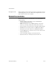
About This Manual This manual contains detailed instructions for installing and configuring your National Instruments NI PXI-8104 embedded controller kit. How to Use the Documentation Set Begin by reading the NI PXI-8104 Installation Guide, a brief quick-start guide that describes how to install and get started with your controller. This manual, the NI PXI-8104 User Manual, contains more details about changing the installation or configuration from the defaults and using the hardware.
About This Manual monospace bold Bold text in this font denotes the messages and responses that the computer automatically prints to the screen. This font also emphasizes lines of code that are different from the other examples. Related Documentation The following documents contain information you may find helpful as you read this manual: NI PXI-8104 User Manual • PICMG 2.0 R3.0 CompactPCI Specification, PCI Industrial Computers Manufacturers Group • IEEE Standard P1284.
1 Introduction Benefits of PXI The PXI (PCI eXtensions for Instrumentation) industry standard, an open specification governed by the PXI Systems Alliance (PXISA), defines a compact modular PC platform for test, measurement, and control systems. PXI leverages the PCI bus, which is the de facto standard for today’s desktop computer software and hardware designs.
Chapter 1 Introduction NI PXI-8104 Description The NI PXI-8104 PXI/CompactPCI embedded computer is a high-performance PXI/CompactPCI system controller. The NI PXI-8104 controller integrates standard I/O features in a single unit by using state-of-the-art packaging. Combining an NI PXI-8104 embedded controller with a PXI-compatible chassis, such as the NI PXI-1042, results in a fully PC-compatible computer in a compact, rugged package.
Chapter 1 Introduction Socket 479 CPU SO-DIMM DDR2 SDRAM PC2-5300 DUAL CH CHIPSET Graphics Memory Controller Hub Gigabit Ethernet DVI-I Connector DMI Flash ROM CHIPSET I/O Controller Hub 4 Hi-Speed USB Connectors PXI Connector PCI Bus ATA 100 IDE Interface PXI Triggers LPC Bus SATA SMB to PXI Trigger LPT 1 Super I/O COM 1 Watchdog Timer SMB Figure 1-1. NI PXI-8104 Block Diagram The NI PXI-8104 consists of the following logic blocks on the CPU module and the I/O module.
Chapter 1 Introduction • The Chipset 945GMCH (Graphics and Memory Controller Hub) connects to the CPU, DDR2 SDRAM, and DVI-I video. • The SMB to PXI Trigger provides a routable connection of the PXI triggers to/from the SMB on the front panel. • The Watchdog Timer block consists of a watchdog timer that can reset the controller or generate a trigger. • The Chipset ICH7M connects to the PCI, USB, IDE, SATA, and LPC buses. • The USB Connectors are connected to the ICH7M chipset.
Chapter 1 Introduction LabVIEW is a powerful and easy-to-use graphical programming environment you can use to acquire data from thousands of different instruments including USB, IEEE 488.2, VXI, serial, PLCs, and plug-in boards. LabVIEW helps you convert acquired data into meaningful results using powerful data analysis routines. Add-on tools provide additional specialized functionality. For more information visit ni.com/labview and ni.com/toolkits.
Chapter 1 Introduction You can expand the timing and triggering functionality of your PXI system with PXI Timing and Synchronization products. These products provide precision clock sources, custom routing of triggers for multi-chassis synchronization, clock sharing, and more and are programmed with NI-Sync. For more information visit ni.com/pxi. NI-VISA is the National Instruments implementation of the VISA specification.
Installation and Configuration 2 This chapter contains information about installing and configuring your NI PXI-8104 controller. Installing the NI PXI-8104 This section contains general installation instructions for the NI PXI-8104. Consult your PXI chassis user manual for specific instructions and warnings. 1. Plug in your chassis before installing the NI PXI-8104. The power cord grounds the chassis and protects it from electrical damage while you install the module.
Chapter 2 Installation and Configuration 1 1 Protective Screw Cap (4X) Figure 2-1. Removing Protective Screw Caps 5. Make sure the injector/ejector handle is in its downward position. Align the NI PXI-8104 with the card guides on the top and bottom of the system controller slot. Caution Do not raise the injector/ejector handle as you insert the NI PXI-8104.
Chapter 2 Installation and Configuration 10. Connect the keyboard and mouse to the appropriate connectors. If you are using a PS/2 keyboard and a PS/2 mouse, a Y-splitter adapter is available to connect both to a single USB connector. Refer to Figure 4-1, Y-Splitter Cable. 11. Connect the DVI monitor video cable to the DVI connector. If you are using a VGA monitor, use the DVI-to-VGA adapter included with your kit. 12. Connect devices to ports as required by your system configuration. 13.
Chapter 2 Installation and Configuration How to Remove the Controller from the PXI Chassis The NI PXI-8104 controller is designed for easy handling. To remove the unit from the PXI chassis, complete the following steps: 1. Power off the chassis. 2. Remove any cables that may be attached to the controller front panel. 3. Unscrew the bracket-retaining screws in the front panel. Refer to Figure 2-1 for the location of these screws. 4. Press the injector/ejector handle down. 5.
Chapter 2 Installation and Configuration Use the following keys to navigate through the BIOS setup: • Left Arrow, Right Arrow—Use these keys to move between the different setup menus. If you are in a submenu, these keys have no effect, and you need to press to leave the submenu first. (To use the arrows on the numeric keypad, you must turn off Num Lock.) • Up Arrow, Down Arrow—Use these keys to move between the options within a setup menu.
Chapter 2 Installation and Configuration • IDE Channel 0 Master—These items display the IDE/ATA devices detected in the system. Normally, you do not need to modify these items. However, if an IDE/ATA device is not autodetected properly, you can specify it manually by pressing on an item. • System Information—This setting displays a screen containing important system information about the NI PXI-8104 controller.
Chapter 2 Installation and Configuration Integrated Peripherals Submenu Use this submenu to apply nondefault configurations to the front panel peripherals of an NI PXI-8104 controller. Normally, you do not need to modify these settings, as the factory default settings provide the most compatible and optimal configuration possible. Note • Serial Port A—This setting enables or disables COM1.
Chapter 2 Installation and Configuration PXI Setup Menu Use this menu to control and route certain signals on the PXI backplane. Normally, you do not need to modify these settings. However, other sections of this manual may indicate that modifications are necessary and may lead to unpredictable behavior. • APIC Routing—This item is valid only for Windows XP and 2000 and other modern operating systems. Select Enabled to initialize the IOAPIC and local APIC in uniprocessor mode.
Chapter 2 Installation and Configuration • Password on Boot—This setting controls whether or not a password is required to boot the system. If enabled, the user must enter the User Password to boot the system. The default setting is Disabled. • Write Protect Boot Sector—When set to Yes, this setting prevents modification of a hard disk boot sector via INT 13h services, which may help prevent certain computer viruses from infecting the controller.
Chapter 2 Installation and Configuration • Load Setup Defaults—This setting restores all BIOS settings to the factory default. This is useful if the controller exhibits unpredictable behavior due to an incorrect or inappropriate BIOS setting. Notice that any nondefault settings such as boot order, passwords, and keyboardless operation are restored to their factory defaults. This may produce undesirable behavior, and in heavily customized cases, may cause the controller to malfunction or fail to boot.
Chapter 2 Installation and Configuration 3 1 1 Normal Operation (Default) 2 Clear CMOS Contents 2 3 Pin 1 Figure 2-3. Clearing the CMOS Contents Drivers and Software Files and Directories Installed on Your Hard Drive Your hard drive includes a directory called images in its root that contains software and soft copies of manuals for the installed devices. The directory structure under the images directory is logically organized into several levels.
Chapter 2 Installation and Configuration c:\images\manuals and list the contents of that directory. You will see several files, one corresponding to each device. The os directory contains a subdirectory corresponding to the operating system installed on your controller. The rest of the directories correspond to each device in your controller. Within each of these directories are the drivers for the devices.
Chapter 2 Installation and Configuration Figure 2-4. Multichassis Configuration in MAX Basic PXI System Configuration 1. Launch MAX. 2. In the Configuration tree, click the Devices and Interfaces branch to expand it. 3. If the PXI system controller has not yet been configured, it is labeled PXI System (Unidentified). Right-click this entry to display the pop-up menu, then select the appropriate controller model from the Identify As submenu. 4. Click the PXI System controller.
Chapter 2 Installation and Configuration through the Identify As submenu. Further expanding the PXI System branch shows all devices in the system that can be recognized by NI-VISA. When your controller and all your chassis are identified, the required pxisys.ini file is complete. The PXI specification allows many combinations of PXI chassis and system modules. To assist system integrators, the manufacturers of PXI chassis and system modules must document the capabilities of their products.
Chapter 2 Installation and Configuration National Instruments has tested and verified that the DDR2 SO-DIMMs we sell work with the NI PXI-8104. We recommend you purchase your DDR2 SO-DIMM modules from National Instruments. Other off-the-shelf DDR2 SO-DIMM modules are not guaranteed to work properly. Note 1 1 DDR2 SO-DIMM Module 2 2 DDR2 SO-DIMM Socket Figure 2-5.
Chapter 2 Installation and Configuration If you need to recover your factory-installed operating system from a CD, you can use the included OS re-installation CD with an external CD-ROM drive such as a USB CD-ROM drive. Boot the PXI controller using the OS re-installation CD to recover the OS. You also may need to reinstall other software after using the CD to recover the OS. Recovering the OS erases the contents of your hard disk. Back up any files you want to keep.
3 I/O Information Front Panel Connectors Table 3-1 lists various I/O interfaces and their corresponding NI PXI-8104 external connectors, bus interfaces, and functions. Table 3-1.
Chapter 3 I/O Information Front Panel 2.847 [72.31] 1.997 [50.72] 2.221 [56.41] 2.328 [59.13] Figure 3-1 shows the front panel layout and dimensions of the NI PXI-8104. Dimensions are in inches [millimeters]. 4.393 [111.58] 3.840 [97.53] 3.551 [90.19] 3.165 [80.38] 2.490 [63.24] 2.063 [52.4] 1.546 [39.26] 1.069 [27.15] 2.847 [72.31] .775 [19.69] .000 [0] .000 [0] Figure 3-1. NI PXI-8104 Front Panel Layout and Dimensions NI PXI-8104 User Manual 3-2 ni.
Chapter 3 I/O Information DVI-I Figure 3-2 shows the location and pinouts for the DVI-I connector on the NI PXI-8104. Table 3-2 lists and describes the DVI-I connector signals. 17 9 1 24 C3 C5 C4 8 C1 C2 Figure 3-2. DVI-I Connector Location and Pinout Table 3-2.
Chapter 3 I/O Information Table 3-2. DVI-I Connector Signals (Continued) Pin NI PXI-8104 User Manual Signal Name 13 Reserved 14 +5 V Power 15 Ground (for +5 V) 16 Hot Plug Detect 17 TMDS Data0– 18 TMDSData0+ 19 TMDS Data0/5 Shield 20 Reserved 21 Reserved 22 TMDS Clock Shield 23 TMDS Clock+ 24 TMDS Clock– C1 Analog Red C2 Analog Green C3 Analog Blue C4 Analog Horizontal Sync C5 Analog GND Return: (analog R, G, B) 3-4 ni.
Chapter 3 I/O Information COM1 Figure 3-3 shows the location and pinouts for the COM1 connector on the NI PXI-8104. Table 3-3 lists and describes the COM1 connector signal. 5 9 COM1 6 1 Figure 3-3. COM1 Connector Location and Pinout Table 3-3.
Chapter 3 I/O Information Ethernet Figure 3-4 shows the location and pinouts for the Ethernet connector on the NI PXI-8104. Table 3-4 lists and describes the Ethernet connector signals. 1 Ethernet 8 Figure 3-4. Ethernet Connector Location and Pinout Table 3-4.
Chapter 3 I/O Information Table 3-5. 10/100/1000 LAN Connector LED States LED Top Bottom Color LED State Condition Off LAN link is not established. On (steady state) LAN link is established. On (brighter and pulsing) The controller is communicating with another computer on the LAN. Unlit Off 10 Mbit/sec data rate is selected. Green On 100 Mbit/sec data rate is selected. Orange On 1000 Mbit/sec data rate is selected.
Chapter 3 I/O Information Table 3-6.
Chapter 3 I/O Information Universal Serial Bus Figure 3-6 shows the location and pinouts for the Universal Serial Bus (USB) connectors on the NI PXI-8104. Table 3-7 lists and describes the USB connector signals. 4 1 USB Figure 3-6. USB Connector Location and Pinout Table 3-7.
Chapter 3 I/O Information Trigger The TRG connector is the software-controlled trigger connection for routing PXI triggers to or from the backplane trigger bus. A trigger allocation process is needed to prevent two resources from connecting to the same trigger line, resulting in the trigger being double-driven and possibly damaging the hardware. At the time of this manual’s publication, this software is not yet available for Windows. Contact National Instruments for more information.
Chapter 3 I/O Information Front Panel Features The NI PXI-8104 controller has the following front-panel features: • A controller reset pushbutton (press the button to generate a reset to the controller) • Two front panel LEDs that show PC status – – The POWER OK LED indicates the power status of the controller.
4 Common Configuration Questions This chapter answers common configuration questions you may have when using the NI PXI-8104 embedded controller. General Questions What do the LEDs on the NI PXI-8104 front panel mean? Refer to the LED status descriptions in the Front Panel Features section of Chapter 3, I/O Information. How do I check the configuration of the memory, hard drive, time/date, and so on? You can view these parameters in the BIOS setup.
Chapter 4 Common Configuration Questions • An external USB mass storage device such as a USB hard drive or CD-ROM • An external USB floppy drive • Most PCI-based boards that provide an Option ROM Note There are some limitations when booting from a USB device. Windows XP can be installed from a USB CD-ROM, but earlier versions of Windows cannot. The NI PXI-8104 BIOS configures the USB devices so that they will work in a DOS environment.
Chapter 4 Common Configuration Questions What if I don’t have a Y-splitter cable? Can I still use a mouse and keyboard? If you do not have a Y-splitter cable, plug a USB keyboard into any USB connector. You can also plug a USB mouse into any USB connector. How do I connect a standard 25-pin LPT cable to the NI PXI-8104? The NI PXI-8104 uses a type C LPT connector. Most parallel port devices use a type A connector.
Chapter 4 Common Configuration Questions Upgrade Information How do I upgrade system memory? You can change the amount of installed RAM on the NI PXI-8104 by upgrading the DDR2 SO-DIMM. To upgrade the RAM, remove the NI PXI-8104 from the PXI chassis. To optimize both memory capacity and system performance, use the same size and speed memory module in each of the two module slots.
Chapter 4 1 1 DDR2 SO-DIMM Module Common Configuration Questions 2 2 DDR2 SO-DIMM Socket Figure 4-2. Installing a DDR2 SO-DIMM in an NI PXI-8104 Controller How do I flash a new BIOS? You can download the new BIOS from ftp.ni.com/support/pxi/. For more information, refer to KnowledgeBase 3H3COSD8. Where do I get the latest software drivers? The latest National Instruments software is available from ni.com/ downloads/. For peripheral drivers, refer to KnowledgeBase 3H3COSD8 at ni.com.
Chapter 4 Common Configuration Questions PXI Configuration How do I use the SMB trigger on the front panel? For details, refer to the PXI Features section of Chapter 2, Installation and Configuration. Why doesn’t the NI PXI-8104 work with the PXI-8220 or PXI-8221? A serialized IRQ conflict with the PXI-8220/8221 and the NI PXI-8104 prevents PC cards using ISA interrupts from working with the NI PXI-8104 controller. For more information, refer to KnowledgeBase 2G3ED80Z at ni.com/support.
5 Troubleshooting This chapter answers common troubleshooting questions you may have when using the NI PXI-8104 embedded computer. What if the NI PXI-8104 does not boot? Several problems can cause a controller not to boot. Here are some things to look for and possible solutions. Things to Notice: • Which LEDs come on? The Power OK LED should stay lit. The Drive LED should blink during boot as the disk is accessed.
Chapter 5 Troubleshooting My controller boots fine until I get to Windows, at which point I cannot read the screen. This may include garbled output, white screen, black screen, or an out of synch message from the monitor. This problem usually results from having the video card output set past the limits of the monitor. You will need to boot Windows in Safe Mode. To do this, reboot the controller. As Windows begins to boot, hold down . You should now be able to reset the video driver to lower settings.
Chapter 5 Troubleshooting As an alternative method, complete the following steps: 1. Power off the chassis. 2. Remove the controller from the chassis. 3. Move the jumper on W7 from pins 1–2 to pins 2–3 as shown in Figure 5-1. 4. Wait one second. Move the jumper back to pins 1–2. 5. Reinstall the controller in the chassis. Caution Do not leave the jumper on pins 2–3. Doing so decreases battery life. Also, the controller will not boot.
A Specifications This appendix lists the electrical, mechanical, and environmental specifications of the NI PXI-8104 embedded computer. NI PXI-8104 CPU Intel® Celeron® M 440 (1.86 GHz single-core processor) On-die L2 cache 1024 KB Dual-Channel DDR2 RAM 1 512 MB (533 MHz) Module Standard, 2 GB Maximum (2 slots available) Hard Drive 60 GB (SATA), minimum Ethernet 10/100/1000 BaseTX Video DVI-I GPIB (IEEE 488.
Appendix A Specifications Electrical Current (A) Voltage (V) Typical Maximum +3.3 2.5 A 3.25 A +5 3.5 A 5.5 A +12 5 mA 5 mA –12 0A 0A Physical Board dimensions ...................................PXI 3U-size module 8.1 cm × 13 cm × 21.6 cm (3.2 in. × 5.1 in. × 8.5 in.) Slot requirements ....................................One system slot plus three controller expansion slots Compatibility ..........................................Fully compatible with PXI specification Weight ...............
Appendix A Specifications Operating Environment Ambient temperature range.................... 5 to 50 °C in an NI PXI-1042 chassis (Tested in accordance with IEC-60068-2-1 and IEC-60068-2-2). Refer to the datasheet linked from the NI PXI-8104 Embedded Controller product page at ni.com for other controller/chassis combinations. Relative humidity range ......................... 10% to 90%, noncondensing (Tested in accordance with IEC-60068-2-56.) Clean the NI PXI-8104 with a soft nonmetallic brush.
Appendix A Specifications Nonoperating ...................................5 to 500 Hz, 2.4 grms (Tested in accordance with IEC-60068-2-64. Nonoperating test profile exceeds the requirements of MIL-PRF-28800F, Class 3.
Appendix A Specifications Environmental Management National Instruments is committed to designing and manufacturing products in an environmentally responsible manner. NI recognizes that eliminating certain hazardous substances from our products is beneficial not only to the environment but also to NI customers. For additional environmental information, refer to the NI and the Environment Web page at ni.com/environment.
Technical Support and Professional Services B Visit the following sections of the award-winning National Instruments Web site at ni.com for technical support and professional services: • Support—Technical support resources at ni.com/support include the following: – Self-Help Technical Resources—For answers and solutions, visit ni.
Appendix B Technical Support and Professional Services • Declaration of Conformity (DoC)—A DoC is our claim of compliance with the Council of the European Communities using the manufacturer’s declaration of conformity. This system affords the user protection for electromagnetic compatibility (EMC) and product safety. You can obtain the DoC for your product by visiting ni.com/certification.
Glossary Symbol Prefix Value n nano 10 –9 μ micro 10 – 6 m milli 10 –3 k kilo 10 3 M mega 10 6 G giga 10 9 T tera 10 12 Symbols ° Degrees. Ω Ohms. % Percent. A A Amperes. AC Alternating Current. ASIC Application-specific integrated circuit.
Glossary B B Bytes. backplane An assembly, typically a printed circuit board, with connectors and signal paths that bus the connector pins. BIOS Basic Input/Output System—BIOS functions are the fundamental level of any PC or compatible computer. BIOS functions embody the basic operations needed for successful use of the computer’s hardware resources. C C Celsius. cache Small portion of high-speed memory used for temporary storage of frequently used data.
Glossary DRAM Dynamic RAM (Random Access Memory)—Storage that the computer must refresh at frequent intervals. DVI-I Direct Video Interface, Integrated—A video technology enabling the use of both analog and digital video signals. E ECP Extended Capabilities Parallel. EEPROM Electronically Erasable Programmable Read Only Memory. EMC Electromagnetic Compatibility. EMI Electromagnetic interference. EPP Enhanced Parallel Port.
Glossary I I/O Input/output—The techniques, media, and devices used to achieve communication between machines and users. IDE Integrated Drive Electronics—Hard disk and built-in controller. IEEE Institute of Electrical and Electronics Engineers. in. Inches. instrument driver A set of routines designed to control a specific instrument or family of instruments, and any necessary related files for LabWindows/CVI or LabVIEW. interrupt A means for a device to request service from another device.
Glossary MB Megabytes of memory. MTBF Mean time between failure. MTTR Mean time to repair. N NI-488 or NI-488.2 The National Instruments software for GPIB systems. NI-DAQ The National Instruments software for data acquisition instruments. NI-VISA The National Instruments implementation of the VISA standard—An interface-independent software that provides a unified programming interface for VXI, GPIB, and serial instruments.
Glossary R RAM Random Access Memory—the computer’s primary workspace. RAMDAC Random Access Memory Digital to Analog Converter—the VGA controller chip that maintains the color palette and converts data from memory into analog signals for the monitor. resource Hardware settings used by devices in a computer system, including ISA interrupt level, DMA channel, and I/O address. RMS Root mean squared. See also grms.
Glossary V V Volts. VGA Video Graphics Array—The minimum video display standard for all PCs. W W Watts.
Index A common configuration questions boot options, 4-1 cables and connections, 4-2 chassis configuration, 2-12 figure, 2-13 driver installation, 4-3 general questions, 4-1 PXI configuration, 4-6 upgrade information, 4-4 CompactPCI specification, 1-1 configuration, common questions boot options, 4-1 cables and connections, 4-2 chassis configuration, 2-12 figure, 2-13 driver installation, 4-3 general questions, 4-1 PXI configuration, 4-6 upgrade information, 4-4 connectors COM1 connector and signals, 3-5 D
Index D F data storage, 3-11 DDR SO-DIMMs installing, 2-14, 4-4 figure, 2-15, 4-5 DDR2 SO-DIMMs from National Instruments (note), 2-15, 4-4 Declaration of Conformity (NI resources), B-2 diagnostic tools (NI resources), B-1 directories and files installed on hard drive, 2-11 documentation conventions used in manual, vii how to use this documentation set, vii NI resources, B-1 related documentation, viii DRIVE LED, 3-11 drivers, 2-11 installation video, 4-3 NI resources, B-1 obtaining latest drivers, 4-5 D
Index K connectors, 3-1 COM1 connector and signals, 3-5 DVI-I connector and signals (table), 3-3 parallel port connector and signals, 3-7 trigger connector and signals, 3-10 Universal Serial Bus (USB) connector and signals, 3-9 data storage, 3-11 front panel dimensions, 3-2 features, 3-11 LEDs, 4-1 system reset pushbutton, 3-11 functional overview, 1-2 hard drive recovery, 2-15 installing DDR SO-DIMMs (figure), 2-15, 4-5 installing in a PXI chassis, 2-1 figure, 2-3 logic blocks, 1-3 peripheral expansion o
Index O S operating environment specifications, A-2, A-3 os directory, 2-11 OS installation from CD-ROM, 2-16 safety specifications, A-4 serial port, 3-1 See also COM1 connector shock and vibration specifications, A-3 socket 479 1 CPU, 1-3 SO-DIMM logic block, 1-3 software See also drivers installed on your hard drive, 2-11 installing from CD-ROM, 4-3 LabVIEW, 1-5 LabWindows/CVI, 1-5 Measurement Studio, 1-5 National Instruments software, 1-4 NI resources, B-1 NI-DAQmx, 1-5 NI-VISA, 1-6 specifications CE
Index T V technical support, B-1 training and certification (NI resources), B-1 trigger, 3-10, 4-6 connector location and pinout (figure), 3-10 connector signals (table), 3-10 troubleshooting CMOS reset, 5-2 controller does not boot, 5-1 damaged module, 5-2 NI resources, B-1 video display, 5-2 video, 3-1 driver installation, 4-3 W Web resources, B-1 Y Y-splitter cable figure, 4-2 using mouse and keyboard without, 4-3 using with PS/2 mouse and keyboard, 2-3 U Universal Serial Bus (USB), 3-1, 3-9 conne