Computer-Based Instruments NI PXI-562x User Manual High-Speed Frequency-Domain Digitizer NI PXI-562x User Manual July 2002 Edition Part Number 322949C-01
Support Worldwide Technical Support and Product Information ni.
Important Information Warranty The NI PXI-5620 and the NI PXI-5621 is warranted against defects in materials and workmanship for a period of one year from the date of shipment, as evidenced by receipts or other documentation. National Instruments will, at its option, repair or replace equipment that proves to be defective during the warranty period. This warranty includes parts and labor.
Compliance FCC/Canada Radio Frequency Interference Compliance* Determining FCC Class The Federal Communications Commission (FCC) has rules to protect wireless communications from interference. The FCC places digital electronics into two classes. These classes are known as Class A (for use in industrial-commercial locations only) or Class B (for use in residential or commercial locations). Depending on where it is operated, this product could be subject to restrictions in the FCC rules.
Canadian Department of Communications This Class B digital apparatus meets all requirements of the Canadian Interference-Causing Equipment Regulations. Cet appareil numérique de la classe B respecte toutes les exigences du Règlement sur le matériel brouilleur du Canada. Compliance to EU Directives Readers in the European Union (EU) must refer to the Manufacturer’s Declaration of Conformity (DoC) for information** pertaining to the CE Mark compliance scheme.
Contents About This Manual Conventions ...................................................................................................................ix Related Documentation..................................................................................................x Chapter 1 Taking Measurements with the NI PXI-562x Installing the Software and Hardware ...........................................................................1-1 Configuring and Testing the Digitizer ............................
About This Manual The NI PXI-562x is a single-channel high-speed digitizer module whose dynamic range and resolution are optimized for frequency-domain analysis applications in research, product design and validation, and manufacturing test. This manual provides information on installing, connecting signals to, and acquiring data from the NI PXI-562x. This manual also provides an overview of the features, functionality, and use of the NI PXI-562x high-speed digitizer module.
About This Manual Related Documentation The following documents contain information that you might find helpful as you read this manual: NI PXI-562x User Manual • NI PXI-5620 Specifications • NI PXI-5621 Specifications • NI-SCOPE User Manual • Spectral Measurements Toolset User Guide x ni.
1 Taking Measurements with the NI PXI-562x The NI PXI-5620 is a 64 Ms/s, 14-bit frequency-domain digitizer module optimized for the best possible noise and distortion performance in a 5–25 MHz passband. It has a –3 dB front-end bandwidth from 10 kHz to 36 MHz, and is always AC-coupled, meaning it does not admit DC components of a signal. The NI PXI-5621 is a DC-coupled version of the NI PXI-5620, optimized for a passband of 0–25 MHz.
Chapter 1 Taking Measurements with the NI PXI-562x 3. a. Insert your NI-SCOPE CD into your CD drive. If installation does not start automatically, navigate to your CD drive and click setup.exe. b. To install both the instrument driver and ADE examples, select the Programmatic and Interactive Support option when prompted. Install the Spectral Measurements Toolset (SMT) CD, if included. The SMT provides frequency-domain functionality and examples.
Chapter 1 Taking Measurements with the NI PXI-562x 3. Find the NI 562x in the list. Notice the device number assigned to your NI 562x. You need this device number to program your NI 562x. 4. Right-click the device name, and select Properties from the menu. 5. From the Properties window, click Test Resources to test the device resources. A dialog box appears and indicates if the resource test has passed. 6. Click Run Test Panels to run the functional test panels and begin using your NI 562x.
Chapter 1 Taking Measurements with the NI PXI-562x For more detailed VI and function help, refer to the NI-SCOPE VI Reference Help and the NI-SCOPE Function Reference Help, located at Start»Programs»National Instruments»NI-SCOPE. Safety Information The following section contains important safety information that you must follow when installing and using the product. Do not operate the product in a manner not specified in this document. Misuse of the product can result in a hazard.
Chapter 1 Taking Measurements with the NI PXI-562x Operate this product only at or below the installation category stated in the NI PXI-5620 Specifications and the NI PXI-5620 Specifications documents. The following is a description of installation categories: • Installation Category I is for measurements performed on circuits not directly connected to MAINS1. This category is a signal level such as voltages on a printed wire board (PWB) on the secondary of an isolation transformer.
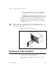
Chapter 1 Taking Measurements with the NI PXI-562x Below is a diagram of a sample installation. NI PXI-562x User Manual 1-6 ni.
2 Hardware Overview This chapter provides an overview of the features and functionality of the NI 562x. How the NI 562x Works A signal follows this path through the NI 562x to the host computer: 1. The signal enters the NI 562x through the analog front panel connector, INPUT. Refer to the Connecting Signals section to find more about the front panel. 2. The signal is filtered and conditioned. Gain and dither are applied to the signal.
Chapter 2 Hardware Overview Connecting Signals Figure 2-2 shows the NI 562x front panel, which contains three connectors: two SMA connectors and an SMB connector. One of the SMA connectors, INPUT, is for attaching the analog input signal you want to measure. The second SMA connector, REF CLK IN, is a 50 Ω, 10 MHz, AC-coupled reference input. The SMB connector, PFI1, is for external digital triggers. 562x 64 MS/s Digitizer INPUT 50 +20 dBm MAX REF CLK IN 50 +16 dBm MAX PFI 1 Figure 2-2.
Chapter 2 Hardware Overview Conditioning the Signal—Impedance, Dither, Gain, and AC Coupling To minimize distortion, signals receive a minimal amount of conditioning. Gain and coupling are nonadjustable. The NI PXI-5620 is AC coupled, meaning it rejects any DC signal components. The NI PXI-5621 is DC coupled, meaning its wider passband acquires DC signal components also. Both versions of the NI 562x digitizer module have a set input impedance of 50 Ω and may apply dither to the input signal.
Chapter 2 Hardware Overview Incorporating the DDC Optionally, you can route the data through the DDC before storing it in onboard memory. The DDC is a digital signal processing (DSP) chip, the Intersil HSP50214B. The first stage uses a digital quadrature mixer that shifts a signal to baseband from any frequency within the range of the digitizer. The next stage decimates (reduces the sample rate) by an integer from 4–16,384.
Chapter 2 Hardware Overview Block Diagram The block diagram below illustrates the operation of the NI 562x. An explanation of some of these features follows. Digital Downconverter Dither Analog Input (INPUT) + Filter Data Path Logic ADC Onboard Memory MITE (PXI Interface) P X I PLL Phase Detector Voltage Controlled Oscillator TIO (Timing and Control) 10 MHz Reference Input (REF CLK IN) CalDAC Trigger and Clock Routing PXI Trigger External Trigger EXT TRIG (PFI) CLK 10 Figure 2-3.
Chapter 2 Hardware Overview a free-running state, in which the acquisition clock is not synchronized to any external reference. The voltage controlled crystal oscillator (VCXO) is a 64 MHz clock. The trigger and clock routing area directs clock signals and triggers. The TIO is the timing engine used for the NI 562x. The MITE is the PXI bus interface. The MITE provides high-speed direct memory access (DMA) transfers from the NI 562x to the host computer memory.
Chapter 2 Hardware Overview Figure 2-4 shows a timing diagram of a multiple-record acquisition. 1 Trigger 2 3 500 ns Acquisition In Progress Buffer 1 1 2 2 = Trigger Not Accepted (Pretrigger Points Not Acquired) = Trigger Not Accepted (500 ns Dead Time) 3= Trigger Not Accepted (Acquisition in Progress) = Trigger Accepted Figure 2-4. Multiple-Record Acquisition Timing Diagram Triggering You can externally trigger the NI 562x through the digital line, PFI1.
Chapter 2 Hardware Overview Synchronizing Multiple PXI Devices The NI 562x uses a PLL to synchronize the 64 MHz sample clock to a 10 MHz reference clock. You can either supply the reference clock through the SMA connector (REF CLK IN) on the front panel or use the system reference clock on the PXI backplane.
Technical Support and Professional Services A Visit the following sections of the National Instruments Web site at ni.com for technical support and professional services: • Support—Online technical support resources include the following: – Self-Help Resources—For immediate answers and solutions, visit our extensive library of technical support resources available in English, Japanese, and Spanish at ni.com/support.
Glossary Prefix Meanings Value p- pico 10 –12 n- nano- 10 –9 µ- micro- 10 – 6 m- milli- 10 –3 k- kilo- 10 3 M- mega- 10 6 G- giga- 10 9 Symbols % percent + positive of, or plus – negative of, or minus / per ° degree ± plus or minus Ω ohm < less than A A amperes A/D analog-to-digital AC alternating current © National Instruments Corporation G-1 NI PXI-562x User Manual
Glossary AC coupled allowing the transmission of AC signals while blocking DC signals ADC analog-to-digital converter—an electronic device, often an integrated circuit, that converts an analog voltage to a digital number ADC resolution the resolution of the ADC, which is measured in bits. An ADC with 16 bits has a higher resolution, and thus a higher degree of accuracy, than a 12-bit ADC.
Glossary CMRR common-mode rejection ratio—a measure of an instrument’s ability to reject interference from a common-mode signal, usually expressed in decibels (dB) coupling the manner in which a signal is connected from one location to another D data path logic a signal router dB decibel—the unit for expressing a logarithmic measure of the ratio of two signal levels: dB = 20log10 V1/V2, for signals in volts dBm decibels with reference to 1 mW, the standard unit of power level used in RF and microw
Glossary drivers software that controls a specific hardware instrument DSP digital signal processor E EEPROM electrically erasable programmable read-only memory—ROM that can be erased with an electrical signal and reprogrammed F FFT fast Fourier transform filtering a type of signal conditioning that allows you to remove unwanted signals or frequency components from the signal you are trying to measure G gain the factor by which a signal is amplified, sometimes expressed in decibels H hardware
Glossary input bias current the current that flows into the inputs of a circuit input impedance the measured resistance and capacitance between the input terminals of a circuit instrument driver a set of high-level software functions that controls a specific plug-in DAQ board. Instrument drivers are available in several forms, ranging from a function callable language to a virtual instrument (VI) in LabVIEW.
Glossary N noise an undesirable electrical signal—noise comes from external sources such as the AC power line, motors, generators, transformers, fluorescent lights, soldering irons, CRT displays, computers, electrical storms, welders, radio transmitters, and internal sources such as semiconductors, resistors, and capacitors. Noise corrupts signals you are trying to send or receive. O Ohm’s Law (R = V/I)—the relationship of voltage to current in a resistance onboard memory the device memory.
Glossary R R resistor RAM random-access memory random interleaved sampling (RIS) method of increasing sample rate by repetitively sampling a repeated waveform real-time sampling sampling that occurs immediately record length the size of a chunk (or record) of data that can be or has been acquired by a device resolution The smallest amount of input signal change that an instrument or sensor can detect. Resolution can be expressed in bits, in proportions, or in percent of full scale.
Glossary Shannon Sampling Theorem a theorem stating that a signal must be sampled at least twice as fast as the bandwidth of the signal to accurately reconstruct the signal as a waveform source impedance a parameter of signal sources that reflects current-driving ability of voltage sources (lower is better) and the voltage-driving ability of current sources (higher is better) system noise a measure of the amount of noise seen by an analog circuit or an ADC when the analog inputs are grounded T temper
Glossary Verror voltage error vertical sensitivity the smallest voltage change a device can detect VI virtual instrument—(1) a combination of hardware and/or software elements, typically used with a PC, that has the functionality of a classic stand-alone instrument (2) a LabVIEW software module (VI), which consists of a front panel user interface and a block diagram program Vrms volts, root mean square value W waveform shape the shape the magnitude of a signal creates over time working voltage t
Index A dead time, in multiple-record acquisitions, 2-6 diagnostic resources, A-1 digital downconverter.
Index O gain, 2-3 input impedence, 2-3 online technical support, A-1 help professional services, A-1 technical support, A-1 P phase detector, 2-5 phase-locked loop (PLL), 2-5 phone technical support, A-1 professional services, A-1 programmatically acquiring data, 1-3 programming examples, A-1 PXI devices, multiple, synchronizing, 2-8 PXI installation, 1-1 I incorporating DDC, 2-4 input impedence, 2-3 installing software and hardware, 1-1 instrument drivers, A-1 K KnowledgeBase, A-1 R M REF CLK IN
Index T V technical support, A-1 telephone technical support, A-1 TIO (timing engine), 2-6 training customer, A-1 trigger and clock routing area, 2-6 triggering digital trigger sources (figure), 2-7 overview, 2-7 troubleshooting resources, A-1 voltage controlled crystal oscillator (VCXO), 2-6 © National Instruments Corporation W Web professional services, A-1 technical support, A-1 worldwide technical support, A-1 I-3 NI PXI-562x User Manual