PXI NI PXI-1056 User Manual NI PXI-1056 User Manual September 2005 371551A-01
Support Worldwide Technical Support and Product Information ni.
Important Information Warranty The NI PXI-1056 is warranted against defects in materials and workmanship for a period of one year from the date of shipment, as evidenced by receipts or other documentation. National Instruments will, at its option, repair or replace equipment that proves to be defective during the warranty period. This warranty includes parts and labor.
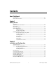
Contents About This Manual Conventions ...................................................................................................................vii Related Documentation..................................................................................................viii Chapter 1 Getting Started Unpacking ......................................................................................................................1-1 What You Need to Get Started ..........................................
Contents Remote Voltage, Temperature, and Fan Monitoring..................................................... 2-9 Serial Communication Command Set............................................................. 2-10 Terminal Settings.............................................................................. 2-10 RS-232 Command Syntax ................................................................ 2-10 PXI System Configuration with MAX .......................................................................
About This Manual The NI PXI-1056 User Manual contains information about installing, configuring, using, and maintaining the NI PXI-1056 18-slot chassis. Conventions The following conventions are used in this manual: » The » symbol leads you through nested menu items and dialog box options to a final action. The sequence File»Page Setup»Options directs you to pull down the File menu, select the Page Setup item, and select Options from the last dialog box.
About This Manual Related Documentation The following documents contain information that you might find helpful as you read this manual: NI PXI-1056 User Manual • CompactPCI Specification PICMG 2.0 R 3.0 • PXI Hardware Specification, Revision 2.2 • PXI Software Specification, Revision 2.2 • IEEE 1101.1-1991, IEEE Standard for Mechanical Core Specifications for Microcomputers Using IEC 603-2 Connectors • IEEE 1101.
1 Getting Started This chapter describes the key features of the PXI-1056 chassis and lists the kit contents and optional equipment you can order from National Instruments. Unpacking Carefully inspect the shipping container and the chassis for damage. Check for visible damage to the metal work. Check to make sure all handles, hardware, and switches are undamaged. Inspect the inner chassis for any possible damage, debris, or detached components.
Chapter 1 Getting Started Table 1-1. AC Power Cables Power Cable Reference Standards Standard 120 V (USA) NEMA 5-15 Switzerland 220 V SEV Australia 240 V AS C112 Universal Euro 230 V CEE (7), II, IV, VII IEC83 North America 240 V NEMA 6-15 United Kingdom 230 V BS 1363/IEC83 If you are missing any of the items listed in Table 1-1, or if you have the incorrect AC power cable, contact National Instruments.
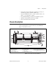
Chapter 1 Getting Started • Temperature-sensing module that can adjust fan speed based on air-intake temperature to minimize audible noise • Front-panel LEDs that indicate a voltage regulation failure, a fan failure, or over-temperature condition • Programmable PXI trigger routing between PXI bus segments • Optional carrying handle and feet for portability • Front rack mount brackets and handles Chassis Description Figures 1-1 and 1-2 show the key features of the PXI-1056 chassis front and rear
Chapter 1 Getting Started 1 8 6 2 2 3 3 2 2 4 1 2 3 4 5 7 Fan Filter Cover Power Supply Shuttle Retainer Screws (x4) Power Supply Shuttle Handles (x2) Chassis Ground Screw Circuit Breaker 6 7 8 5 Universal AC Inlet Fan Speed Selector Switch RS-232 Connector for Remote Voltage/Temperature/Fan Monitoring Figure 1-2. Rear View of the PXI-1056 Chassis Optional Equipment Contact National Instruments to order the following options for the PXI-1056 chassis.
Chapter 1 Getting Started PXI-1056 Backplane Overview Interoperability with CompactPCI The PXI-1056 backplane is interoperable with 5 V and universal PXI-compatible products and standard CompactPCI products. This is an important feature, because some PXI systems may require components that do not implement PXI-specific features. For example, you may want to use a standard CompactPCI network interface card in a PXI chassis.
Chapter 1 Getting Started The star trigger slot can also be used to provide a PXI_CLK10 signal to the backplane. For more information regarding PXI_CLK10, refer to the System Reference Clock section. Peripheral Slots There are 17 3U-sized peripheral slots including the star trigger slot. Three of these slots can only be used for 3U modules. The chassis has a number of peripheral slots that can also be used in a 6U configuration.
© National Instruments Corporation 1-7 System Controller 2 2 Star Trigger Controller Local Bus 3 Local Bus 4 5 PXI Trigger Bus Buffer Switch 1 and PCI to PCI Bridge 1 PXI Trigger Bus Segment 1/PCI Bus Segment 1 1 PXI Star Triggers Local Bus Local Bus 7 Local Bus 8 Local Bus 9 Local Bus 10 PXI Trigger Bus Segment 2/PCI Bus Segment 2 6 PXI-1056 Backplane Configuration Local Bus 12 PXI Trigger Bus Buffer Switch 2 and PCI to PCI Bridge 2 11 System Reference Clock Buffer and Detection
Chapter 1 Getting Started Trigger Bus All slots on each PXI bus segment share eight PXI trigger lines. You can use these trigger lines in a variety of ways. For example, you can use triggers to synchronize the operation of several different PXI peripheral modules. In other applications, one module located in slot 2 can control carefully timed sequences of operations performed on other modules in the system.
Installation and Configuration 2 This chapter describes how to install, configure, and use the PXI-1056 chassis. Before connecting the chassis to a power source, read this chapter and the Read Me First: Safety and Radio-Frequency Interference document included with your chassis. Safety Information Before undertaking any troubleshooting, maintenance, or exploratory procedure, carefully read the following caution notices.
Chapter 2 Installation and Configuration personnel operating the chassis. Furthermore, damage or fire may occur if replacement parts are unsuitable. • Modification—Do not modify any part of the chassis from its original condition. Unsuitable modifications may result in safety hazards. Chassis Cooling Considerations The PXI-1056 is designed to operate on a bench or in an instrument rack. Determine how you want to use the PXI-1056 and follow the appropriate installation instructions.
Chapter 2 Installation and Configuration 1 2 1 Air Outlets (Side of Chassis) 2 Air Intake (Back of Chassis) Figure 2-1. PXI-1056 Chassis Airflow Side View Install the chassis so that you can easily access the rear panel. This simplifies replacing the air filter or power supply shuttle, if necessary. Setting Fan Speed The fan-speed selector switch is on the rear panel of the PXI-1056. Refer to Figure 1-2, Rear View of the PXI-1056 Chassis, to locate the fan-speed selector switch.
Chapter 2 Installation and Configuration Rack Mounting Rack-mount applications may require the optional rear rack mount kit available from National Instruments. Refer to Figure A-3, PXI-1056 Rack Mount Components, and the instructions supplied with the rack mount kits to install your PXI-1056 in an instrument rack. You may want to remove the feet from the PXI-1056 when rack mounting. To do so, remove the screws holding the feet in place.
Chapter 2 Installation and Configuration The power switch allows you to power on the chassis or place it in standby mode. Push the power switch to the On (Left) position (if not already on). Observe that the fan becomes operational and the power switch LED is a steady green. Installing a PXI Controller This section contains general instructions for installing a PXI controller in the PXI-1056 chassis. Refer to your PXI controller user manual for specific instructions and cautions.
Chapter 2 Installation and Configuration Figure 2-2. Injector/Ejector Handle Position during Controller or Peripheral Module Insertion 3. When you begin to feel resistance, push up on the injector/ejector handle to inject the controller fully into the chassis frame. Secure the controller front panel to the chassis using the controller front-panel mounting screws. 4. Connect the keyboard, mouse, and monitor to the appropriate connectors.
Chapter 2 Installation and Configuration 1 2 1 3 PXI-1056 Chassis 2 Injector/Ejector Rail 3 NI PXI Controller Figure 2-3. NI PXI Controller Installed in a PXI-1056 Chassis Installing PXI Modules Complete the following steps to install a module. 1. Make sure the power switch is in the Off (Standby) position. 2. Install a module into a chassis slot by first placing the module card edges into the front module guides (left and right), as shown in Figure 2-4.
Chapter 2 Installation and Configuration 1 2 4 3 1 PXI-1056 Chassis 2 PXI Module 3 Injector/Ejector Handle 4 NI PXI Controller Figure 2-4. Installing PXI or CompactPCI Modules Power Switch LED Indicator The chassis power switch has an integrated LED. This LED indicates the chassis is powered on and operating normally.
Chapter 2 Installation and Configuration There are six dual-color LED indicators on the front panel of the chassis. Four of the LEDs indicate the status of voltage supply regulation (+3.3 V, 5 V, +12 V, –12 V). The FAN LED indicates the operational status of the fan. The TEMP LED indicates whether the chassis is maintaining a proper operating temperature, or whether there is an over-temperature condition. The operating temperature of the chassis should not exceed 60 °C.
Chapter 2 Installation and Configuration Serial Communication Command Set Voltage, temperature, and fan speed statuses may be read using the following defined command set. Any monitored parameter having a trip point to indicate a fail status will also generate an autonomous status message to indicate the fault condition. Terminal Settings The communication terminal must be set to the following settings.
Chapter 2 Installation and Configuration Temperature Measurement Commands Note Units are in degrees Celsius.
Chapter 2 Installation and Configuration Command SF Response Description SF:F1: x Fan #1, x = OK or FAIL SF:F2: x Fan #2, x = OK or FAIL SF:F3: x Fan #3, x = OK or FAIL SF:F4: x Fan #4, x = OK or FAIL Voltage Measurement Commands Note Units are in VDC. Command VA Response Description VA: Transmit all voltages as listed below: V1: +X.XXX Voltage of the +3.3VDC Power supply V2: +X.XXX Voltage of the +5VDC Power supply V3: +XX.
Chapter 2 Installation and Configuration Request for All Status Note Voltage units are in VDC, and temperature units are in degrees Celsius. Command SA Response Description MONITOR, 209-2xxx-Cxx-00 Rx Header information SP:PS: x Power supply status, x = OK or FAIL ST:T1: x Temperature sensor #1, x = OK or FAIL ST:T2: x Temperature sensor #2, x = OK or FAIL ST:T3: x Temperature sensor #3, x = OK or FAIL SV:V1: x +3.
Chapter 2 Installation and Configuration Help Menu Requests Note This is not available on older SMM code versions. Command ? Response Commands are 2 letters in length as follows: VA - Report the 4 voltages defined as –V1 = +3.
Chapter 2 Installation and Configuration Figure 2-5. Multichassis Configuration in MAX Basic PXI System Configuration 1. Launch MAX. 2. In the Configuration tree, click on the Devices and Interfaces branch to expand it. 3. If the PXI system controller has not yet been configured, it will be labeled “PXI System (Unidentified).” Right-click on this entry to display the popup menu, then select the appropriate controller model from the Identify As submenu. 4.
Chapter 2 Installation and Configuration 5. Apply the chassis number labels (shown in Figure 2-6) included with your kit to each chassis in your PXI system, and write in the chassis number accordingly in the white space. Figure 2-6. Chassis Number Label Trigger Configuration in MAX Each chassis has one or more trigger buses, each with eight lines numbered 0 through 7 that can be reserved and routed statically or dynamically.
Chapter 2 Installation and Configuration Note Selecting any non-disabled routing automatically reserves the line in all trigger buses being routed to. If you are using NI-DAQmx, it will reserve and route trigger lines for you, so you won’t have to route trigger lines manually. Complete the following steps to configure trigger routings in MAX. 1. In the Configuration tree, select the chassis in which you want to route trigger lines. 2.
3 Maintenance This chapter describes basic maintenance procedures you can perform on the PXI-1056 chassis. Caution Disconnect the power cable prior to servicing the PXI-1056 chassis. Service Interval Clean the chassis fan filter at a maximum interval of six months. Depending on the amount of use and ambient dust levels in the operating environment, the filter may require more frequent cleaning. Clean dust from the chassis exterior (and interior) as needed, based on the operating environment.
Chapter 3 Maintenance Interior Cleaning Use a dry, low-velocity stream of air to clean the interior of the chassis. Use a soft-bristle brush for cleaning around components. Exterior Cleaning Cautions Avoid getting moisture inside the chassis during exterior cleaning, especially through the top vents. Use just enough moisture to dampen the cloth. Do not wash the front- or rear-panel connectors or switches. Cover these components while cleaning the chassis.
Chapter 3 Maintenance Resetting the AC Mains Circuit Breaker If the PXI-1056 is connected to an AC source and encounters an over-current condition, the circuit breaker on the rear panel will trip to prevent damage to the chassis. Complete the following steps to reset the circuit breaker. 1. Set the front-panel power switch to the Off position. 2. Disconnect the AC power cable. 3. Depress the circuit breaker to reset it. 4. Reconnect the AC power cable. 5. Set the power switch to the On position.
Chapter 3 Maintenance Removal The PXI-1056 power-supply shuttle is a replacement part for the PXI-1056 chassis. Before attempting to replace the power-supply shuttle, verify that there is adequate clearance behind the chassis. Set the power switch on the front panel to the Off position. Disconnect the power cable and any other cables from the power-supply shuttle on the rear of the chassis. Identify the 4 screws that attach the power-supply shuttle back cover to the chassis.
A Specifications If the PXI-1056 chassis is used in a manner inconsistent with the instructions or specifications listed by National Instruments, the protective features of the chassis may be impaired. Caution This appendix contains specifications for the PXI-1056 chassis. Electrical AC Input Input voltage range................................. 100–240 VAC Operating voltage range1 ........................ 90–264 VAC Input frequency ......................................
Appendix A Specifications Power disconnect ....................................The AC power cable provides main power disconnect. Depressing the front-panel power switch controls the internal chassis power supply that provides DC power to the CompactPCI/PXI backplane. DC Output DC current capacity (IMP) Voltage 0–55 °C +3.3 V 40 A +5 V 59 A +12 V 9A –12 V 4.5 A Load regulation Voltage Load Regulation +3.3 V <0.5% +12 V <0.5% +5 V <0.5% –12 V <0.
Appendix A Specifications Over-current protection.......................... All outputs protected from short circuit and overload with automatic recovery when the short or overload is removed. Over-voltage protection1 3.3 V, 5 V, +12 V, –12 V................ 130% above nominal output voltage Power-supply shuttle MTTR.................. Replacement in under 5 minutes Chassis Cooling Per slot cooling capacity ........................
Appendix A Specifications Safety The PXI-1056 was designed to meet the requirements of the following standards of safety for electrical equipment for measurement, control, and laboratory use: • EN 61010-1, IEC 61010-1 • UL 61010-1 • CAN/CSA-C22.2 No. 61010-1 Note For UL and other safety certifications, refer to the product label, or visit ni.com/certification, search by model number or product line, and click the appropriate link in the Certification column. Electromagnetic Compatibility EMC......
Appendix A Specifications Environmental Operating temperature............................ 0 to 55 °C Storage temperature ............................... –40 to 71 °C Relative humidity Operating ........................................ 10 to 90% non condensing Nonoperational (storage) ................ 5 to 95% non conducting Shock Operational1,2 .................................. 30 g peak, half sine, 11 ms pulse Nonoperational1,2 ............................
Appendix A Specifications Backplane Size .........................................................3U/6U-sized; one 3U system slot (with three system expansion slots) and 17 3U peripheral slots, or any combination up to 7 6U cards and 3U cards. Compliant with IEEE 1101.10 mechanical packaging. PXI Hardware Specification, Revision 2.2 compliant. Accepts both PXI and CompactPCI (PICMG 2.0 R 3.0) 3U and 6U modules. V(I/O)1 ....................................................
Appendix A Specifications Maximum jitter introduced by backplane circuitry..................... 1 ps RMS in 10 Hz to 1 MHz range Mechanical Overall dimensions (standard chassis) Height.............................................. 177.8 mm (7.0 in.) Note 14.5 mm (0.57 in.) is added to height when feet are installed. Width .............................................. 431.8 mm (17.0 in.) Depth............................................... 457.2 mm (18.0 in.) Weight......................................
Appendix A Specifications .98 (24.9) 17.00 (431.8) 6.98 (177.4) .57 (14.5) 2.29 (58.2) 18.00 (457.2) 1.68 (42.7) Figure A-1. PXI-1056 Dimensions (Front and Side) in Inches (mm) NI PXI-1056 User Manual A-8 ni.
Appendix A Specifications 16.06 (407.9) .74 (18.8) .85 (21.6) 15.28 (388.1) Figure A-2.
Appendix A Specifications Figure A-3 shows the PXI-1056 rack-mount kit components. 2 1 2 1 PXI-1056 Chassis 2 Rack Mount Brackets Figure A-3. PXI-1056 Rack Mount Components NI PXI-1056 User Manual A-10 ni.
B Pinouts This appendix describes the P1 and P2 connector pinouts for the PXI-1056 backplane. Table B-1 shows the P1 (J1) connector pinout for the System Controller slot. Table B-2 shows the P2 (J2) connector pinout for the System Controller slot. Table B-3 shows the P1 (J1) connector pinout for the star trigger slot. Table B-4 shows the P2 (J2) connector pinout for the star trigger slot. Table B-5 shows the P1 (J1) connector pinout for the peripheral slots.
Appendix B Pinouts Table B-1. P1 (J1) Connector Pinout for the System Controller Slot Pin Z A B C D E F 25 GND 5V REQ64# ENUM# 3.3V 5V GND 24 GND AD[1] 5V V(I/O) AD[0] ACK64# GND 23 GND 3.3V AD[4] AD[3] 5V AD[2] GND 22 GND AD[7] GND 3.3V AD[6] AD[5] GND 21 GND 3.3V AD[9] AD[8] M66EN C/BE[0]# GND 20 GND AD[12] GND V(I/O) AD[11] AD[10] GND 19 GND 3.3V AD[15] AD[14] GND AD[13] GND 18 GND SERR# GND 3.3V PAR C/BE[1]# GND 17 GND 3.
Appendix B Pinouts Table B-2.
Appendix B Pinouts Table B-3. P1 (J1) Connector Pinout for the Star Trigger Slot Pin Z A B C D E F 25 GND 5V REQ64# ENUM# 3.3V 5V GND 24 GND AD[1] 5V V(I/O) AD[0] ACK64# GND 23 GND 3.3V AD[4] AD[3] 5V AD[2] GND 22 GND AD[7] GND 3.3V AD[6] AD[5] GND 21 GND 3.3V AD[9] AD[8] M66EN C/BE[0]# GND 20 GND AD[12] GND V(I/O) AD[11] AD[10] GND 19 GND 3.3V AD[15] AD[14] GND AD[13] GND 18 GND SERR# GND 3.3V PAR C/BE[1]# GND 17 GND 3.
Appendix B Pinouts Table B-4.
Appendix B Pinouts Table B-5. P1 (J1) Connector Pinout for the Generic Peripheral Slot Pin Z A B C D E F 25 GND 5V REQ64# ENUM# 3.3V 5V GND 24 GND AD[1] 5V V(I/O) AD[0] ACK64# GND 23 GND 3.3V AD[4] AD[3] 5V AD[2] GND 22 GND AD[7] GND 3.3V AD[6] AD[5] GND 21 GND 3.3V AD[9] AD[8] M66EN C/BE[0]# GND 20 GND AD[12] GND V(I/O) AD[11] AD[10] GND 19 GND 3.3V AD[15] AD[14] GND AD[13] GND 18 GND SERR# GND 3.3V PAR C/BE[1]# GND 17 GND 3.
Appendix B Pinouts Table B-6.
Technical Support and Professional Services C Visit the following sections of the National Instruments Web site at ni.com for technical support and professional services: • Support—Online technical support resources at ni.
Appendix C Technical Support and Professional Services • Calibration Certificate—If your product supports calibration, you can obtain the calibration certificate for your product at ni.com/calibration. If you searched ni.com and could not find the answers you need, contact your local office or NI corporate headquarters. Phone numbers for our worldwide offices are listed at the front of this manual. You also can visit the Worldwide Offices section of ni.
Glossary Symbol Prefix Value p pico 10 –12 n nano 10 –9 µ micro 10 – 6 m milli 10 –3 k kilo 10 3 M mega 10 6 G giga 10 9 T tera 10 12 Symbols ° Degrees. ≥ Equal or greater than. ≤ Equal or less than. % Percent. Ω Ohms. A A Amperes. AC Alternating current. ANSI American National Standards Institute. AUTO Automatic fan speed control. AWG American Wire Gauge.
Glossary B backplane An assembly, typically a printed circuit board, with connectors and signal paths that bus the connector pins. BNC Bayonet Neill Concelman connector; a commonly used coaxial connector. C C Celsius. cfm Cubic feet per minute. CFR Code of Federal Regulations. cm Centimeters. CompactPCI An adaptation of the Peripheral Component Interconnect (PCI) Specification 2.
Glossary E efficiency Ratio of output power to input power, expressed as a percentage. EIA Electronic Industries Association. Embedded system controller A module configured for installation in slot 1 of a PXI chassis. This device is unique in the PXI system in that it performs the system controller functions, including clock sourcing and arbitration for data transfers across the backplane. Installing such a device into any other slot can damage the device, the PXI backplane, or both.
Glossary I IEC International Electrotechnical Commission; an organization that sets international electrical and electronics standards. IEEE Institute of Electrical and Electronics Engineers. IMP Mainframe peak current. in. Inches. inhibit To turn off. J jitter A measure of the small, rapid variations in clock transition times from their nominal regular intervals. Units: seconds RMS. K kg Kilograms. km Kilometers. L lb Pounds. LED Light emitting diode.
Glossary M m Meters. MAX NI Measurement & Automation Explorer, the utility which allows you to configure and test your PXI system. MHz Megahertz. One million Hertz; one Hertz equals one cycle per second. ms Millisecond, one thousandth of a second (10 –3). MTBF Mean time between failure. MTTR Mean time to repair. N NEMA National Electrical Manufacturers Association. NI National Instruments.
Glossary PXI PCI eXtensions for Instrumentation. PXI is an implementation of CompactPCI with added electrical features that meet the high performance requirements of instrumentation applications by providing triggering, local buses, and system clock capabilities. PXI_CLK10 10 MHz PXI system reference clock. R RMS Root mean square. S s Seconds. skew Deviation in signal transmission times. slot blocker An assembly installed into an empty slot to improve the airflow in adjacent slots.
Glossary T TTL Transistor-transistor logic. U UL Underwriter’s Laboratories. V V Volts. VAC Volts alternating current, or Vrms. Vpp Peak-to-peak voltage. W W Watts.
Index A F AC power cables (table), 1-2 fan speed measurement commands, 2-11 filler panel installation, 2-3 C H cables, power (table), 1-2 calibration certificate (NI resources), C-2 chassis initialization file, 2-17 CompactPCI installing modules (figure), 2-8 configuration. See installation, configuration, and operation connector pinouts.
Index L P2 (J2) connector peripheral slot (table), B-7 star trigger slot (table), B-5 system controller slot (table), B-3 power cables (table), 1-2 power supply connecting to, 2-4 remote voltage monitoring and inhibiting connector, 2-9 replacing configuration, 3-4 connecting safety ground, 3-4 connecting to power source, 3-4 installation, 3-4 removal, 3-4 voltages at voltage monitoring connector (D-sub) (table), 2-9 power switch LED indicator, 2-8 power up, testing, 2-4 programming examples (NI resources)
Index support technical, C-1 system controller slot description, 1-5 P1 (J1) connector pinouts (table), B-2 P2 (J2) connector pinouts (table), B-3 star trigger (ST) slot, 1-5 system reference clock, 1-8 trigger bus, 1-8 R rack mount kit dimensions (figure), A-10 related documentation, viii remote voltage monitoring and inhibiting connector pinout (table), 2-9 RS-232 command syntax, 2-10 fan speed measurement commands, 2-11 help menu requests, 2-14 request for all status, 2-13 temperature measurement comm