
NI PCI-6110/6111 User Manual


Appendix C Common Questions
NI PCI-6110/6111 User Manual C-6 ni.com
Caution If you enable a PFI line for output, do not connect any external signal source to
it. Connecting external signals to enabled PFI lines can damage the device, the computer,
and the connected equipment.
What are the power-on states of the PFI and DIO lines on the I/O
connector?
At system power-on and reset, both the PFI and DIO lines are set to
high-impedance by the hardware. This means that the device circuitry is not
actively driving the output either high or low. However, these lines may
have pull-up or pull-down resistors connected to them as shown in
Table 4-3, I/O Signal Summary for the NI PCI-6110/6111. These resistors
weakly pull the output to either a logic high or logic low state. For example,
DIO(0) is in the high impedance state after power-on, and Table 4-3 shows
that there is a 50 kΩ pull-up resistor. This pull-up resistor sets the DIO(0)
pin to a logic high when the output is in a high-impedance state.
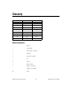
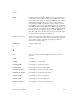
Table C-1. Signal Name Equivalencies
Hardware
Signal Name
LabVIEW
Route Signal
NI-DAQ Select_Signal
AIGATE — ND_IN_EXTERNAL_GATE
AOGATE — ND_OUT_EXTERNAL_GATE
CONVERT* AI Convert ND_IN_CONVERT
SISOURCE — ND_IN_SCAN_CLOCK_TIMEBASE
STARTSCAN AI Scan Start ND_IN_SCAN_START
TRIG1 AI Start Trigger ND_IN_START_TRIGGER
TRIG2 AI Stop Trigger ND_IN_STOP_TRIGGER
UISOURCE — ND_OUT_UPDATE_CLOCK_TIMEBASE
UPDATE* AO Update ND_OUT_UPDATE
WFTRIG AO Start Trigger ND_OUT_START_TRIGGER