Modular Instrumentation NI PCI-5911 User Manual High-Speed Digitizer with Flex ADC ™ NI PCI-5911 User Manual March 2003 Edition Part Number 322150E-01
Support Worldwide Technical Support and Product Information ni.
Important Information Warranty The NI 5911 is warranted against defects in materials and workmanship for a period of one year from the date of shipment, as evidenced by receipts or other documentation. National Instruments will, at its option, repair or replace equipment that proves to be defective during the warranty period. This warranty includes parts and labor.
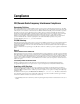
Compliance FCC/Canada Radio Frequency Interference Compliance Determining FCC Class The Federal Communications Commission (FCC) has rules to protect wireless communications from interference. The FCC places digital electronics into two classes. These classes are known as Class A (for use in industrial-commercial locations only) or Class B (for use in residential or commercial locations). All National Instruments (NI) products are FCC Class A products.
Contents About This Manual Conventions ...................................................................................................................vii Related Documentation..................................................................................................viii Safety Information .........................................................................................................viii Chapter 1 Introduction Installing the NI 5911 ......................................................
Contents Memory ......................................................................................................................... 2-10 Triggering and Memory Usage ....................................................................... 2-10 Multi-Record Acquisitions ............................................................................................ 2-11 RTSI Bus and Clock PFI ............................................................................................... 2-11 PFI Lines .....
About This Manual The NI 5911 User Manual provides information on installing, connecting signals to, and acquiring data from your NI 5911 high-speed digitizer. This manual includes an overview of the NI 5911 and explains the operation of each functional unit of the NI 5911. Conventions The following conventions appear in this manual: <> Angle brackets that contain numbers separated by an ellipsis represent a range of values associated with a bit or signal name—for example, DIO<3..0>.
About This Manual Related Documentation The following documents contain information that you might find helpful as you read this manual: • Where to Start with Your NI Digitizer • NI-SCOPE Software User Manual • NI-SCOPE Instrument Driver Quick Reference Guide You can download these documents from ni.com/manuals. Safety Information This section contains important safety information that you must follow when installing and using the device.
About This Manual • Pollution Degree 3 means that conductive pollution occurs, or dry, nonconductive pollution occurs that becomes conductive due to condensation. You must insulate signal connections for the maximum voltage for which the device is rated. Do not exceed the maximum ratings for the device. Do not install wiring while the device is live with electrical signals. Do not remove or add connector blocks when power is connected to the system.
About This Manual outlets in the fixed installation, and stationary motors with permanent connections to fixed installations. • NI PCI-5911 User Manual Installation Category IV is for measurements performed at the primary electrical supply installation (<1,000 V). Examples include electricity meters and measurements on primary overcurrent protection devices and on ripple control units. x ni.
1 Introduction Thank you for buying an NI PCI-5911 digitizer, featuring the Flex ADC for variable speed and resolution. This chapter contains information on installing, connecting signals to, and acquiring data from the NI 5911 Installing the NI 5911 Installation involves the following main steps: 1. Install the NI-SCOPE driver software. You use this driver to write programs to control the NI 5911 in different application development environments (ADEs).
Chapter 1 Introduction The +5 V signal is fused at 1.1 A. However, NI recommends limiting the current from this pin to 30 mA. The fuse is self-resetting. Note CH 0 PFI 1 PFI 2 (DIN) Figure 1-1. NI 5911 Connectors NI PCI-5911 User Manual 1-2 ni.
Chapter 1 9 8 6 1 2 3 +5 V (Fused) GND Reserved 4 5 6 7 5 4 2 1 Reserved Reserved PFI 2 Introduction 3 7 8 9 Reserved Reserved Reserved Figure 1-2. 9-Pin Mini-Circular DIN Connector Acquiring Data with the NI 5911 You can acquire data either programmatically—by writing an application for the NI 5911—or interactively with the Scope Soft Front Panel.
Chapter 1 Introduction NI-SCOPE Function Reference Help, located at Start»Programs» National Instruments»NI-SCOPE. For more detailed VI help, use LabVIEW context-sensitive help (Help»Show Context Help) or the NI-SCOPE VI Reference Help, located at Start»Programs»National Instruments»NI-SCOPE. Interactively Controlling the NI 5911 with the Scope Soft Front Panel The Scope Soft Front Panel allows you to interactively control the NI 5911 as you would a desktop oscilloscope.
2 Hardware Overview This chapter includes an overview of the NI 5911, explains the operation of each functional unit making up the NI 5911, and describes the signal connections. Figure 2-1 shows a block diagram of the NI 5911. Analog Input Connector AC/DC Coupling Protect/ Calibration Mux PGIA A/D Converter 100 MHz, 8-Bit Noise Shaper Calibration Generator Timing I/O, Memory Control Digital I/O Connector Digital Signal Processor Capture Memory Reference Clock Data Figure 2-1.
Chapter 2 Hardware Overview presented at the negative input is subtracted from the signal presented at the positive input. As shown in Figure 2-2, this subtraction removes ground noise from the signal. The inner conductor of the BNC is V+. The outer shell is V–. Input Signal V+ V– + Vout PGIA – Ground Noise Figure 2-2. Signal Noise-Free Measurements Grounding Considerations The path for the positive signal has been optimized for speed and linearity.
Chapter 2 Hardware Overview Input Ranges To optimize the ADC resolution, you can select different gains for the PGIA so that you can scale your input signal to match the full input range of the converter. The NI 5911 PGIA offers seven input ranges, from ±0.1 V to ±10 V, as shown in Table 2-1. Table 2-1. Input Ranges for the NI 5911 Range Input Protection Threshold ±10 V ±10 V ±5 V ±5 V ±2 V ±5 V ±1 V ±5 V ±0.5 V ±5 V ±0.2 V ±5 V ±0.
Chapter 2 Hardware Overview where Vm is the measured voltage, Vs is the source voltage, Rs is the external source impedance, and Rin is the input impedance. If the device you are measuring has a very large output impedance, your measurements will be affected by this impedance divider. For example, if the device has 1 MΩ output impedance, your measured signal is one-half of the actual signal value. Input Bias The inputs of the PGIA typically draw an input bias current of 1 nA at 25 °C.
Chapter 2 Hardware Overview to allow an 8-bit digitizer to acquire accurate data. However, the NI 5911 in flexible resolution mode is much more precise and thus requires a greater number of time constants of settling time to achieve the desired precision. Refer to Appendix A, Digitizer Basics, of the NI-SCOPE Software User Manual, for more information on input coupling.
Chapter 2 Hardware Overview Flexible Resolution Mode Table 2-2 shows the relationship between the available sampling rates, resolution, and the corresponding bandwidth for flexible resolution mode. Table 2-2. Available Sampling Rates and Corresponding Bandwidth in Flexible Resolution Mode Sampling Rate Resolution Bandwidth 12.5 MS/s 11 bits 3.75 MHz 5 MS/s 14 bits 2 MHz 2.5 MS/s 15.5 bits 1 MHz 1 MS/s 17.5 bits 400 kHz 500 kS/s 18 bits 200 kHz 200 kS/s 18.
Chapter 2 Hardware Overview Calibration The NI 5911 can be calibrated for high accuracy and resolution because of an advanced calibration scheme. There are two different types of calibration: internal, or self-calibration, and external calibration. A third option, internal restore, restores factory settings and should be used only in the event of a self-calibration failure. Self-calibration is performed using a software command that compensates for drifts caused by environmental temperature changes.
Chapter 2 Hardware Overview • The linearity of the ADC is calibrated using an internal sine wave generator as reference. • The time-to-digital converter used for RIS measurements is calibrated. Caution Do not apply high-amplitude or high-frequency signals to the NI 5911 during self-calibration. For optimal calibration performance, disconnect the input signal from the NI 5911.
Chapter 2 Analog Input High Level Gain + COMP Analog Trigger Circuit Low Level Hardware Overview ATC_OUT COMP – a. Analog Trigger Circuit Software ATC_OUT RTSI<0..6> Trigger 7 PFI 1, PFI 2 2 Arm b. Trigger and Arm Sources Figure 2-3. Trigger Sources Analog Trigger Circuit The analog trigger on the NI 5911 operates by comparing the current analog input to an onboard threshold voltage. This threshold voltage is the trigger value, and can be set within the current input range in 170 steps.
Chapter 2 Hardware Overview Trigger Holdoff Trigger holdoff is the minimum length of time (in seconds) from an accepted trigger to the start of the next record. In other words, when a trigger is accepted, the trigger counter is loaded with the desired holdoff time. After completing its current record, the digitizer records no data and accepts no triggers until the holdoff counter runs out. When the counter runs out, the next record begins and a trigger may be accepted.
Chapter 2 Hardware Overview Multi-Record Acquisitions After the trigger has been received and the posttrigger samples have been stored, the NI 5911 can be configured to begin another acquisition that is stored in another onboard memory record. This operation is a multi-record acquisition. To perform multi-record acquisitions, configure the NI 5911 to the number of records you want to acquire before starting the acquisition.
Chapter 2 Hardware Overview PFI Lines as Inputs You can select PFI 1 or PFI 2 as inputs for a trigger or a reference clock. Refer to the Synchronization section for more information about the use of reference clocks in the NI 5911. PFI Lines as Outputs You can select PFI 1 or PFI 2 to output several digital signals. Reference Clock is a 10 MHz clock that is synchronous to the 100 MHz sample clock on the NI 5911.
Chapter 2 Hardware Overview route that trigger over the RTSI bus to trigger the other digitizer(s). However, the trigger that is routed to the other digitizer(s) is sent synchronously to an internal 25 MHz clock. For more information about synchronization, refer to the NI-SCOPE Software User Manual.
A Specifications This appendix lists the specifications of the NI 5911. These specifications are typical at 25 °C unless otherwise stated. Acquisition System Bandwidth .............................................. 100 MHz maximum; refer to Table 2-2, Available Sampling Rates and Corresponding Bandwidth in Flexible Resolution Mode Number of channels ............................... 1 Number of flexible resolution ADC....... 1 Max RIS sample rate..............................
Appendix A Specifications Sample Rate Mode Effective Resolution 20 kS/s Flexible Resolution 20.5 bits 10 kS/s Flexible Resolution 21 bits * 1 ≤ n ≤ 224 in conventional mode Sample onboard memory........................4 MB or 16 MB Memory Sample Depth Sampling Frequency Mode Sample Depth (4 MB) Sample Depth (16 MB) 100/n* MS/s Conventional 4 MS 16 MS 12.5 MS/s Flexible Resolution 1 MS 4 MS 5 MS/s Flexible Resolution 1 MS 4 MS 2.
Appendix A Specifications Vertical Sensitivity (Input Ranges) Input Range Noise Referred to Input ±10 V –174 dBfs/ Hz ±5 V –168 dBfs/ Hz ±2 V –160 dBfs/ Hz ±1 V –154 dBfs/ Hz ±0.5 V –148 dBfs/ Hz ±0.2 V –140 dBfs/ Hz ±0.1 V –128 dBfs/ Hz Acquisition Characteristics Accuracy DC gain accuracy ................................... ±0.05% signal ±0.0001% fs for all input ranges at 1 MS/s in flexible resolution mode DC offset accuracy................................. ±0.1 mV ±0.
Appendix A Specifications Filtering Sampling Frequency Bandwidth Ripple Alias Attenuation Conventional 100 MHz ±3 dB N/A 12.5 MS/s Flexible Resolution 3.75 MHz ±0.2 dB –60 dB 5 MS/s Flexible Resolution 2 MHz ±0.1 dB –70 dB 2.5 MS/s Flexible Resolution 1 MHz ±0.05 dB –80 dB 1 MS/s Flexible Resolution 400 kHz ±0.005 dB –80 dB 500 kS/s Flexible Resolution 200 kHz ±0.005 dB –80 dB 200 kS/s Flexible Resolution 80 kHz ±0.
Appendix A Specifications Sampling Frequency Bandwidth Noise Density Total Noise 1 MS/s 400 kHz –160 dBfs/ Hz –104 dBfs 500 kS/s 200 kHz –160 dBfs/ Hz –107 dBfs 200 kS/s 80 kHz –160 dBfs/ Hz –111 dBfs 100 kS/s 40 kHz –160 dBfs/ Hz –114 dBfs 50 kS/s 20 kHz –160 dBfs/ Hz –117 dBfs 20 kS/s 8 kHz –160 dBfs/ Hz –121 dBfs 10 kS/s 4 kHz –160 dBfs/ Hz –124 dBfs * 1 ≤ n ≤ 224 in conventional mode Distortion Sampling Frequency SFDR for Input 0 dBfs SFDR for Input –20 dBfs SFDR fo
Appendix A Specifications Clock jitter ..............................................<75 pSrms, independent of reference clock source Clock compatibility ................................TTL for both input and output Sampling clock frequencies Conventional mode....................... 100/n MHz, where 1 ≤ n ≤224 Flexible resolution mode .................12.5 MHz, 5 MHz, 2.5 MHz, 1 MHz, 500 kHz, 200 kHz, 100 kHz, 50 kHz, 20 kHz, 10 kHz Reference clock sources .........................
Appendix A Specifications Sampling Methods Random interleaved sampling................ 1 GS/s down to 200 MS/s effective sample rate, repetitive signals only Real-time sampling ................................ Up to 100 MS/s sample rate for transient and repetitive signals Power Requirements +5 VDC .................................................. 4 A +12 VDC ................................................ 100 mA –12 VDC ................................................ 100 mA Physical Dimensions......
Appendix A Specifications Calibration Self-calibration (internal calibration) .....Self-calibration is done using a software command. The calibration involves gain, offset and linearity correction for all input ranges and input modes. Interval.............................................1 week, or any time temperature changes beyond ±5 °C. Hardware detects temperature variations beyond calibration limits, which can also be queried by software. External calibration.................................
Appendix A Specifications CE Compliance This product meets the essential requirements of applicable European Directives, as amended for CE Marking, as follows: • Low-Voltage Directive (safety):73/23/EEC • Electromagnetic Compatibility Directive (EMC):89/336/EEC Refer to the Declaration of Conformity (DoC) for this product for any additional regulatory compliance information. To obtain the DoC for this product, click Declarations of Conformity Information at ni.com/hardref.nsf/.
Technical Support and Professional Services B Visit the following sections of the National Instruments Web site at ni.com for technical support and professional services: • Support—Online technical support resources include the following: – Self-Help Resources—For immediate answers and solutions, visit our extensive library of technical support resources available in English, Japanese, and Spanish at ni.com/support.
Appendix B Technical Support and Professional Services If you searched ni.com and could not find the answers you need, contact your local office or NI corporate headquarters. Phone numbers for our worldwide offices are listed at the front of this manual. You also can visit the Worldwide Offices section of ni.com/niglobal to access the branch office Web sites, which provide up-to-date contact information, support phone numbers, email addresses, and current events. NI PCI-5911 User Manual B-2 ni.
Glossary Symbol Prefix Value p pico 10 –12 n nano 10 –9 µ micro 10 – 6 m milli 10 –3 k kilo 10 3 M mega 10 6 G giga 10 9 Symbols % percent + positive of, or plus – negative of, or minus / per ° degree ± plus or minus Ω ohm A A amperes A/D analog to digital AC alternating current © National Instruments Corporation G-1 NI PCI-5911 User Manual
Glossary AC coupled the passing of a signal through a filter network that removes the DC component of the signal ADC analog-to-digital converter—an electronic device, often an integrated circuit, that converts an analog voltage to a digital number ADC resolution the resolution of the ADC, which is measured in bits. An ADC with16 bits has a higher resolution, and thus a higher degree of accuracy, than a 12-bit ADC.
Glossary clock hardware component that controls timing for reading from or writing to groups CMRR common-mode rejection ratio—a measure of an instrument’s ability to reject interference from a common-mode signal, usually expressed in decibels (dB) counter/timer a circuit that counts external pulses or clock pulses (timing) coupling the manner in which a signal is connected from one location to another D dB decibel—the unit for expressing a logarithmic measure of the ratio of two signal levels: dB
Glossary E EEPROM electrically erasable programmable read-only memory—ROM that can be erased with an electrical signal and reprogrammed equivalent time sampling any method used to sample signals in such a way that the apparent sampling rate is higher than the real sampling rate event the condition or state of an analog or digital signal F filtering a type of signal conditioning that allows you to filter unwanted signals from the signal you are trying to measure fs full-scale—total voltage in the i
Glossary input impedance the measured resistance and capacitance between the input terminals of a circuit instrument driver a set of high-level software functions that controls a specific plug-in DAQ board. Instrument drivers are available in several forms, ranging from a function callable language to a virtual instrument (VI) in LabVIEW.
Glossary N noise an undesirable electrical signal—noise comes from external sources such as the AC power line, motors, generators, transformers, fluorescent lights, soldering irons, CRT displays, computers, electrical storms, welders, radio transmitters, and internal sources such as semiconductors, resistors, and capacitors. Noise corrupts signals you are trying to send or receive. Nyquist frequency a frequency that is one-half the sampling rate. See also Nyquist Sampling Theorem.
Glossary pretriggering the technique used on a device to keep a buffer filled with data, so that when the trigger conditions are met, the sample includes the data leading up to the trigger condition PXI PCI eXtensions for Instrumentation. PXI is an open specification that builds off the CompactPCI specification by adding instrumentation-specific features.
Glossary sense in four-wire resistance the sense measures the voltage across the resistor being excited by the excitation current settling time the amount of time required for a voltage to reach its final value within specified limits source impedance a parameter of signal sources that reflects current-driving ability of voltage sources (lower is better) and the voltage-driving ability of current sources (higher is better) system noise a measure of the amount of noise seen by an analog circuit or an
Glossary V V volts VAC volts alternating current VDC volts direct current Verror voltage error VI virtual instrument—(1) a combination of hardware and/or software elements, typically used with a PC, that has the functionality of a classic stand-alone instrument (2) a LabVIEW software module (VI), which consists of a front panel user interface and a block diagram program Vrms volts, root mean square value W waveform shape the shape the magnitude of a signal creates over time working voltage t
Index A location on front panel (figure), 1-2 SMB connector, 1-1 contacting National Instruments, B-2 conventions used in the manual, vii customer education, B-1 professional services, B-1 technical support, B-1 AC coupling, 2-4 accuracy characteristics, A-3 acquisition multiple record, 2-11 Scope Soft Front Panel, 1-4 acquisition characteristics specifications accuracy, A-3 common-mode characteristics, A-3 distortion, A-5 dynamic range, A-4 filtering, A-4 acquisition modes specifications, A-7 acquisition
Index E RTSI bus trigger and clock lines, 2-11 trigger holdoff, 2-10 triggering and arming analog trigger circuit, 2-9 trigger holdoff, 2-10 trigger sources (figure), 2-9 errors during acquisition, 2-8 example code, B-1 F help filtering specifications, A-4 flexible resolution mode available sampling rates (table), 2-6 definition, 2-6 purpose and use, 2-6 frequently asked questions, B-1 professional services, B-1 technical support, B-1 I impedance formula for impedance divider, 2-3 input and output im
Index Declaration of Conformity, B-1 professional services, B-1 system integration services, B-1 technical support, B-1 worldwide offices, B-2 NI 5911 See also hardware overview block diagram, 2-1 connectors BNC connector, 1-1 DIN connector, 1-1 location on front panel (figure), 1-2 SMB connector, 1-1 front panel (figure), 1-2 installing, 1-1 Scope Soft Front Panel, 1-4 specifications acquisition characteristics, A-3 acquisition modes, A-7 acquisition system, A-1 timebase system, A-5 triggering systems, A-
Index T specifications acquisition characteristics accuracy, A-3 common-mode characteristics, A-3 distortion, A-5 dynamic range, A-4 filtering, A-4 acquisition modes, A-7 acquisition system, A-1 calibration, A-8 operating environment, A-7 physical, A-7 power requirements, A-7 storage environment, A-7 timebase system, A-5 triggering systems, A-6 storage environment specifications, A-7 support technical, B-1 synchronization, 2-12 system integration services, B-1 NI PCI-5911 User Manual technical support,