NI MATRIXx DocumentIt User Guide TM DocumentIt User Guide April 2007 370769C-01 TM
Support Worldwide Technical Support and Product Information ni.
Important Information Warranty The media on which you receive National Instruments software are warranted not to fail to execute programming instructions, due to defects in materials and workmanship, for a period of 90 days from date of shipment, as evidenced by receipts or other documentation. National Instruments will, at its option, repair or replace software media that do not execute programming instructions if National Instruments receives notice of such defects during the warranty period.
Conventions The following conventions are used in this manual: » The » symbol leads you through nested menu items and dialog box options to a final action. The sequence File»Page Setup»Options directs you to pull down the File menu, select the Page Setup item, and select Options from the last dialog box. This icon denotes a note, which alerts you to important information. bold Bold text denotes items that you must select or click in the software, such as menu items and dialog box options.
Contents Chapter 1 Introduction Manual Organization .....................................................................................................1-1 DocumentIt and the Rapid Prototyping Concept ...........................................................1-2 Automatic Document Generation Process .....................................................................1-4 Cruise Control Example.................................................................................................
Contents Appendix E Generating Documents Using Microsoft Word Appendix F Generating ASCII Documents Appendix G Technical Support and Professional Services Index DocumentIt User Guide vi ni.
1 Introduction With SystemBuild and DocumentIt menu options, you can generate high-quality design documentation automatically from SystemBuild block diagrams. This guide provides the information you need to start using DocumentIt, as well as the more advanced details necessary to customize the generated design documentation.
Chapter 1 Introduction • Appendix B, Generating Documents Using FrameMaker, provides a description of how to generate a sample design document using DocumentIt and FrameMaker templates. • Appendix C, Generating 2167A Documents Using FrameMaker, provides a description of how to generate a sample design document conforming closely with DOD-STD-2167A using DocumentIt and FrameMaker templates.
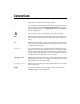
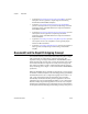
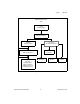
Chapter 1 Introduction MATRIXx Product Family Tools Xmath (Analysis/Design) SystemBuild (Modeling/Simulation) AutoCode (Code Generation) DocumentIt (Document Generation) ASCII Output Document Real Time Hardware Cross-Compilers/ Real-Time Operating System FRFrameMaker MMS Word InInterleaf (pSOS or VxWorks) (Implementation on an embedded processor) Figure 1-1.
Chapter 1 Introduction Automatic Document Generation Process As an integral part of MATRIXx Rapid Prototyping concept, DocumentIt lets you generate design documentation from a SystemBuild block diagram model quickly, automatically, and without programming skills. DocumentIt details the software design in a uniform standardized documentation format and fully supports the SystemBuild hierarchical approach to system design.
Chapter 1 Introduction SystemBuild/Xmath Model Simulation Step 1 SystemBuild Model File Step 2 Interleaf Markup Template* (.rtf) Step 2 DocumentIt Design Documentation Generator Command Options (.dac) FrameMaker Markup Template* Step 3 Standard ASCII Document Document with FrameMaker Markup Cmds. Standard Template File Document with Interleaf Markup Cmds.
Chapter 1 Introduction for a specialized purpose. DocumentIt output in this case is an ASCII text file, which you can use with almost any text editor. You can edit the file or print it as a simple unformatted ASCII file. Typically, the template file contains DocumentIt parameters and publishing commands such as rich text format (RTF) or FrameMaker markup language (MML), which DocumentIt writes directly to the output file. 3. Generate the design document.
Chapter 1 Introduction Figure 1-3. Cruise Control SystemBuild Diagram The cruise control model consists of the highest-level SuperBlock, two embedded SuperBlocks, and associated units. Figure 1-4 shows the associated SuperBlock Properties dialog. Click Help for information on each field in the dialog.
Chapter 1 Introduction Figure 1-4. SuperBlock Properties for Cruise Control Diagram The information from the SuperBlock Properties dialog can be included in the DocumentIt ASCII output file by using the appropriate keywords in the template file. The excerpt from a template file shown in Example 1-1 produces entries in the DocumentIt ASCII output file shown in Example 1-2.
Chapter 1 Num Ext. In Num Ext. Out Num SuperBlocks Attribute Frequency = = = = = Introduction @num_sb_in_i@ @num_sb_out_i@ @num_blks_in_sb_i@ @sb_attr_s@ @sb_freq_r@ Has Input Data = @sb_has_in_data_b@ @ENDSEGMENT@ Example 1-2 DocumentIt ASCII Output File ================================== Software Design Document Overview : This cruise controller regulates vehicle speed around a set point.
Chapter 1 Introduction System States and Models: Num Ext. In Num Ext. Out Num SuperBlocks Attribute Frequency = = = = = This model is enabled and disabled externally. 3 1 3 Discrete 50.0000 Has Input Data = 1 Similarly, information from all SuperBlock/block dialogs and input/output description dialogs can be included within an ASCII output file by the appropriate use of the keywords in the template file.
Chapter 1 Introduction Related Publications National Instruments provides a complete library of publications to support its products.
Invoking DocumentIt 2 This chapter tells how to generate documents from SystemBuild, Xmath, and from the operating system prompt. How to Generate Design Documentation Using DocumentIt, you can generate design documentation from: • SystemBuild—generates a real-time file (.rtf) and then extracts block and SuperBlock documentation from a model using the Generate Documentation dialog (the recommended method). • Xmath—generates an .
Chapter 2 Invoking DocumentIt 3. Select your options. The available options include: Block Parameters Select the source of the %Var information: %Vars from Xmath—uses the latest values of the Xmath variables. Block Defaults—uses the block’s default values. 4. Typecheck If selected, the Analyzer checks for matching data types for input and output signals. AutoCode generates the appropriate data types in the target language that correspond to the SystemBuild data types.
Chapter 2 Invoking DocumentIt Platform Specific Differences The DocumentIt Generate Documentation dialog has some platform-specific features. Windows SystemBuild uses the standard Windows selection dialog to display an output file name in the File name field. The Look in field displays the working directory which will be the output directory for your generated file. You can select any drive or directory for the generated file.
Chapter 2 Invoking DocumentIt UNIX The Generate Documentation dialog uses a standard Motif File Selection dialog to specify the name of the output documentation file in the Selection field. DocumentIt User Guide Filter Displays the file selection directory path. Uses standard shell wildcard character(s) to select the files shown in the Files listing. Default value is the current directory with the *.cat filter.
Chapter 2 Selection Invoking DocumentIt Displays the complete path to the file selected in the Files listing. Because this name is used for both the RTF file and the documentation file, any extensions will be stripped before creating the .rtf and source file names.
Chapter 2 Invoking DocumentIt where name1 identifies the model to be processed for documentation generation. The model can be either: • A string in quotes (“”), which must be the name of a SuperBlock that exists in the current SystemBuild Catalog. This SuperBlock is analyzed and processed to generate documentation. • A variable, not in quotes. Variables should be assigned to a string, the string must be the name of a SuperBlock in the current catalog.
Chapter 2 Invoking DocumentIt Generating Documentation from the OS If a model file already exists, it is also possible to execute DocumentIt from the operating system prompt. The input file for processing must be a real-time file (.rtf). At the operating system prompt, execute the command: % autostar {options} model_file.rtf Many of the options are the same as the fields in the documentation generation dialog. Refer to Appendix A, DocumentIt Options, for a complete list of DocumentIt options.
Chapter 2 Invoking DocumentIt number of blocks: @num_blks_in_sb_i@ block list: @LOOPP j=0, j lt num_blks_in_sb_i, j=j plus 1@@ @SCOPE BLOCK j@@ block name: @blk_name_s@ block ID: @blk_id_i@ block type: @blk_typ_s@ block inputs: @num_blk_in_i@ block outputs: @num_blk_out_i@ @ENDLOOPP@@ --------------------------------------------------@ENDLOOPP@@ @ENDSEGMENT@@ DocumentIt uses the TPL formatting language, such
Chapter 2 Invoking DocumentIt block name: Block block ID: 46 block type: Logical Operator -- AND-OR-NOT block inputs: 2 block outputs: 1 Pseudocode for the process of generating text for a SuperBlock is shown in Example 2-3. Example 2-3 Pseudocode for Generating a Textual Printout of a Model
Customizing the Generated Documentation 3 You can customize DocumentIt-generated output documentation to suit your specific needs by using templates. Template files are ASCII files containing text, interspersed with template command parameters that specify DocumentIt output.
A DocumentIt Options This appendix provides additional information about invoking DocumentIt. Use this appendix together with Chapter 2, Invoking DocumentIt. Options When Invoking DocumentIt As described in Chapter 2, Invoking DocumentIt, DocumentIt can be invoked from the Catalog Browser, the Xmath Commands window, or the operating system prompt. Table A-1 lists the various DocumentIt options. From the Catalog Browser, select Tools»DocumentIt. From the Xmath Commands window, enter the following command.
Appendix A DocumentIt Options Table A-1. Command Options when Invoking DocumentIt (Continued) Xmath Option OS Option Description model This Xmath option is used for creating the .rtf file. When invoking from the OS, the .rtf file must already exist; therefore, there is no OS option equivalent. A text string representing the name of a SuperBlock in the SystemBuild Editor—for example, System. msrtf -msw1 Provides special parsing for Microsoft Word documentation generation.
Appendix A DocumentIt Options Table A-1. Command Options when Invoking DocumentIt (Continued) Xmath Option OS Option tpldac Description A string specifying the location of the template dac file to be used in document generation. Default file is $XMATH/ -d ../case/DIT/templates/ascii/ documentit.dac (the code template dac). tplsrc A string specifying the location of the template file to be used in document generation. The default file is -t $XMATH/../case/DIT/templates/ ascii/documentit.
Appendix A DocumentIt Options file, the command option overrides the same option in the options file. Refer to Example A-1 and the following paragraphs. For different applications, you might need to invoke DocumentIt differently. For this reason, you can have multiple options files. To invoke DocumentIt with an options file other than autostar.opt, specify the name of the options file when you invoke DocumentIt. Refer to Example A-2 and the following paragraphs.
Appendix A Example A-2 DocumentIt Options Example Options File Called myopt.opt // Sample options file // -t c386_c860_mb2.tpl -o myoutput2 To use this file, invoke DocumentIt as follows: autostar -doc -opt myopt.opt model.rtf This invokes DocumentIt with the myopt.opt options file. If you have both of the above option files in your directory, as shown in Examples A-1 and A-2, invoking autostar without the -opt option puts the generated documentation into the myoutput file. The autostar.
B Generating Documents Using FrameMaker This appendix provides instructions for using the FrameMaker documentation example.
Appendix B Generating Documents Using FrameMaker Table B-1. FrameMaker Example Files Filename Description fmgp.tpl This template file determines what information will be extracted from the model to create an ASCII output file. Additionally, fmgp.tpl embeds FrameMaker MML commands, which define how the document will be formatted when it is imported into FrameMaker. Finally, the template also embeds an MML command that calls the include file fmgpinc.
Appendix B Generating Documents Using FrameMaker Table B-2. FrameMaker MML Commands (Continued) Command Description Indented text paragraph which can be used to align with the text in a numbered list (first level number). Indented text paragraph which can be used to align with the text in a numbered list (second level number). First level bulleted list. Second level bulleted list. Chapter title.
Appendix B Generating Documents Using FrameMaker Table B-2. FrameMaker MML Commands (Continued) Command Description Indented paragraph that aligns with the text in the NOTE paragraph. The word NOTE is not included. This is used when a note has a second paragraph. Revision of the document on the title page. Refer to Figure B-2. Automatically numbered table caption.
Appendix B Generating Documents Using FrameMaker 8. With the Block Parameters combo box, select %Vars from Xmath. 9. In the Template File field, specify fmgp.tpl as the template file. 10. Select the Typecheck checkbox. 11. To generate the MML document file, click OK. Changing the Generic Title Page The MML file that you have generated—in this case, Controller_Logic.mml—includes a generic title page that appears as shown in Figure B-1 after it is imported into FrameMaker.
Appendix B Generating Documents Using FrameMaker Figure B-1. Generic Title Page DocumentIt User Guide B-6 ni.
Appendix B Generating Documents Using FrameMaker Software Design Document Author's Name X.X January 27, 1994 Company Name Street Address City, State ZIP Figure B-2. Title Page Data in fmgp.tpl and controller_logic_gen.mml Generating an .eps file from SystemBuild 1. To place an illustration in your FrameMaker document, you must insert an anchored frame where you want the figure to appear.
Appendix B Generating Documents Using FrameMaker location you specified. Use the FrameMaker capture feature to capture and import the figure that you want into the anchored frame. • If you are familiar with FrameMaker, you can create an anchored frame and import the figure you want directly into your FrameMaker document by completing the following steps. a. Highlight the top level SuperBlock (Controller_Logic). b.
Appendix B Generating Documents Using FrameMaker Putting Information in Table Format 1. Page through the document to ensure it meets your needs. If you have information that you want in table format, complete the following steps, beginning with step a. If you have no tables, skip to step 2. a. Select all the data you want to include in the table, but do not include the last paragraph symbol in the last row of table data.
Appendix B Generating Documents Using FrameMaker d. Delete any extraneous paragraph symbols that may have appeared below the table during the conversion process. This is necessary due to the way FrameMaker converts tables. e. Complete steps a through d for each table you have in the document. 2. From the pull-down menu, select File»Generate. 3. Click List Table of Contents, then click Generate. 4. Leave all the current settings in the Set Up Table of Contents dialog intact and click OK. 5.
Appendix B 8. Generating Documents Using FrameMaker Select the fmgpTOC.doc frame. From the File pull-down menu, select Save As. You must specify the identical path and file name as you did in the previous step for your new document file, only add TOC to the file name before the extension. Refer to the following example. Original File Name New File Name fmgp.doc FMsample1.doc fmgpTOC.doc FMsample1TOC.
C Generating 2167A Documents Using FrameMaker This appendix describes how to use the FrameMaker 2167A example. This includes describing how to: • Generate documents and encapsulated PostScript files. • Import encapsulated PostScript files into a generated document automatically and manually. • Format table data for FrameMaker.
Appendix C Generating 2167A Documents Using FrameMaker Table C-1. FrameMaker 2167A Example Files Filename Description fmmil.tpl This template file determines what information will be extracted from the model to create an ASCII output file. Additionally, fmmil.tpl embeds FrameMaker MML commands, which define how the document will be formatted when it is imported into FrameMaker. Finally, the template also embeds an MML command that calls the include file fmmilinc.
Appendix C Generating 2167A Documents Using FrameMaker Table C-2. FrameMaker 2167A MML Commands (Continued) Command Description Second level bulleted list. Title page CDRL sequence number. Refer to Figure C-2. Chapter heading level. Title page entry for the name of the client for whom the document was prepared. Refer to Figure C-2. Title page entry for the contract number. Refer to Figure C-2. Document title. Refer to Figure C-2.
Appendix C Generating 2167A Documents Using FrameMaker Table C-2. FrameMaker 2167A MML Commands (Continued) Command Description Table caption. Title page entries. Refer to Figure C-2. Title page CSCI name and system name entries. Refer to Figure C-2.
Appendix C Generating 2167A Documents Using FrameMaker Changing the Generic Title Page The MML file that you have generated—in this case, controller_logic_mil.mml—includes a generic title page that appears as shown in Figure C-1 after it is imported into FrameMaker. If you want to change the data on the title page, you can accomplish this in one of the three following ways: • Using a text editor, you can edit the fmmil.tpl data. Figure C-2 shows the data in the fmmil.
Appendix C Generating 2167A Documents Using FrameMaker Revision X.X: June 12, 2000 National Instruments Corp. Figure C-1. Generic Title Page DocumentIt User Guide C-6 ni.
Appendix C Generating 2167A Documents Using FrameMaker Revision X.X: June 12, 2000 Software Design Document For The CSCI NAME Of System Name XXXXXXX XXXXXXXXXXX Prepared for: Contracting Agency Name, Department Code Prepared by: Figure C-2. Title Page Data in fmmil.tpl and controller_logic_mil.mm Generating an .
Appendix C Generating 2167A Documents Using FrameMaker • Using a text editor, you can insert the tpl function @small_frame( )@ (5 in. × 5 in. frame) or @large_frame( )@ (7 in. × 5 in. frame) in fmgp.tpl where you want the figure to appear. You should make these changes to fmgp.tpl before you generate the document from SystemBuild. After the document is processed and imported into FrameMaker, a blank frame will be placed into your document in the location you specified.
Appendix C Generating 2167A Documents Using FrameMaker 4. Click Copy File into Document. 5. Select Controller_Logic_mil.mml and click OK. 6. After the import is complete, you will still have a blank page except for a single paragraph text symbol at the top of the page. Select the paragraph symbol and delete it. The Software Design Document title page will fill the page. Note Do not save this file until you are prompted to do so.
Appendix C Generating 2167A Documents Using FrameMaker 3. You can also click and drag to highlight one or more table columns. Click the left mouse to grab the left column handles, and pull out or push in to resize the column. 4. Delete any extraneous paragraph symbols that may have appeared below the table during the conversion process. This is necessary due to the manner in which FrameMaker converts tables. 5. Complete the steps 1 through 4 for each table you have in the document. 6.
Appendix C Generating 2167A Documents Using FrameMaker 11. Select the fmmilTOC.doc frame. From the File pull-down menu, select Save As. Now, you must specify the identical path and file name as you did in the previous step for your new document file, only add TOC to the file name before the extension. Refer to the following example. Original File Name New File Name fmmil.doc FMsample1.doc fmmilTOC.doc FMsample1TOC.
D Generating 2167A Documents Using Interleaf Here are instructions for using the Interleaf 2167A example. This tutorial tells how to: • Generate documents and encapsulated PostScript files. • Import epsf files into a generated document automatically and manually. • Format table data for Interleaf.
Appendix D Generating 2167A Documents Using Interleaf Table D-1. Interleaf 2167A Example Files Filename Description ilmil.tpl This template file determines what information will be extracted from the model to create an ASCII output file. Additionally, ilmil.tpl embeds Interleaf markup commands, which define how the document will be formatted when it is opened under Interleaf.
Appendix D Generating 2167A Documents Using Interleaf Table D-2. Interleaf Markup Commands (Continued) Command Description <“dummy”> First paragraph on the title page. This is an empty place holder required to provide the correct spacing from the top of the page. <“FIGcap”> Automatically numbered figure caption. <“head1”> First heading level (for example, 1.1). <“head2”> Second heading level (for example, 1.1.1). <“head3”> Third heading level (for example, 1.1.1.1).
Appendix D Generating 2167A Documents Using Interleaf Generating the 2167A Document To generate the sample 2167A document using DocumentIt and Interleaf, complete the following steps: Note If you want to generate a document from your own model, follow the same steps given in this example, but use your own model for document generation. 1. 2. From your system prompt, go to your Interleaf desktop directory (do not invoke Interleaf) using the change directory command.
Appendix D Generating 2167A Documents Using Interleaf DocumentIt using ilmil.tpl will continue to have your new title page until you change the contents of ilmil.tpl again. • Using a text editor you can edit the ASCII output file you have just generated. Figure D-2 shows the data in the example file controller_logic_mil.asc that produces the title page shown in Figure D-1. If you regenerate the document, you will have to edit this file again.
Appendix D Generating 2167A Documents Using Interleaf Revision X.X: November 26, 1999 National Instruments Corp. Figure D-1. Generic Title Page DocumentIt User Guide D-6 ni.
Appendix D Generating 2167A Documents Using Interleaf <“Rev”> Revision X.X: November 26, 1999 <“DocTitle”> Software Design Document <“TitlePar1”> For The <“TitlePar2”> CSCI NAME <“TitlePar1”> Of <“TitlePar2”> System Name <“contract”> XXXXX.XX <“CDRL”> XXXXXX.nnn <“PrepFor”> Prepared for: <“Client”> Contracting Agency Name, Department Code <“PrepBy”> Prepared by: <“Author”> National Instruments Corporation Figure D-2. Title Page Data in ilmil.tpl and controller_logic_mil.
Appendix D Generating 2167A Documents Using Interleaf Adding a Plot or SystemBuild Diagram to an Interleaf Document 1. To place a plot or SystemBuild diagram in your Interleaf document, complete the following steps: a. Use the hardcopy command to create a PostScript file of each plot or SystemBuild diagram you want to include. b. Convert each PostScript file to an Interleaf image file. The following diagram illustrates the conversion process (using psfilt) for each PostScript file. file.
Appendix D Page # = Diagram = Generating 2167A Documents Using Interleaf Autonum, V11, (g9,1,0, (i18,1,0,,0,0,8.5333325,0,0,10.9999992,0,0,2559,3299,1,0,7,0,0,8.5333325,10 .999 9992,673657859,1,2559,0,0,3299,0,0,2559,3299,0,0,0,0,0,2559,3299,1,255, @sb_mangled_name_s.ps1.img,2,639,0,0,824,0,0,2559,3299,0,0,0,0,0,486,674,1, 1,3157(X0,3157,FBC8FCFCFCFCFCFCFCFCFCFCFCFCFCFCFCFCFCFCFCFCFCFCFCFCFCFCFCFC FCFCFCFC . . .
E Generating Documents Using Microsoft Word This appendix describes how to use the Microsoft Word documentation example. This includes describing how to: • Generate documents and encapsulated PostScript files. • Import Enhanced Metafile (.emf) files into a generated document automatically and manually. • Format table data for Microsoft Word.
Appendix E Generating Documents Using Microsoft Word Table E-1. Microsoft Word Documentation Example Files Files in %CASE%\DIT\templates\msword\general: mswgp.tpl The template file you must specify when using DocumentIt to generate an ASCII output file for use with the Word general purpose documentation. It determines what information is extracted from the model to create an ASCII output file. mswgp.wrd This is a template file included in the mswgp.tpl file.
Appendix E Generating Documents Using Microsoft Word 7. In the File Name field, enter Controller_Logic.doc. This output file is created in your working directory unless you specify another path. 8. With the Block Parameters combo box, select %Vars from Xmath. 9. In the Template File field, specify msgwp.tpl as the template file. 10. Click the Typecheck checkbox. 11. Click the MS Word checkbox. 12. To generate the document file, click OK.
Appendix E Generating Documents Using Microsoft Word 4. From the Format pull-down menu, select Enhanced Metafile. 5. From the Output pull-down menu, select Separate files. 6. (Optional) You can use the Files of type pull-down menu to display .emf files only. 7. DocumentIt User Guide Click OK. E-4 ni.
Appendix E 8. Generating Documents Using Microsoft Word By default DocumentIt automatically includes all the SuperBlock diagrams in the generated document. This is done by inserting template function @include_img@ under every SuperBlock scope where the image is to be included. The template mswgp.tpl is written to handle only importing .emf files into the Word document. The generated document has links to the .emf files in your local directory.
Appendix E Generating Documents Using Microsoft Word • Using a text editor, you can edit the output document you have just generated. If you are familiar with RTF format, you can search for title generation and modify it there. If you regenerate the document, you have to edit this file again. 2. Generate a new DocumentIt output file. 3. Start Microsoft Word. 4. From the File pull-down menu, select Open. 5. In the Open dialog, select Controller_Logic.doc and click OK.
Appendix E Generating Documents Using Microsoft Word Importing Graphics 1. To place an illustration in your document manually, you must insert an anchored frame in the page where you want the figure to appear. You can insert an anchored frame in your document by selecting the Insert pull-down menu. A blank frame will be placed into your document in the location you specified. 2. Now you can select Picture under the Insert pull-down menu. There, you can select the graphics file you want to import.
Appendix E Generating Documents Using Microsoft Word Table Data Do not include last paragraph symbol of table data Figure E-2. Marking Data for Table Formatting 1. From the pull-down menu, select Table»Convert Text to Table. When the Convert Text to Table dialog appears, select AutoFormat and select Grid 5 under that. Then leave the settings intact and click OK for the AutoFormat, and click OK for the Text to Table dialog. You can choose any design under the AutoFormat. 2.
Appendix E 3. Generating Documents Using Microsoft Word Leave all the current settings in the Set Up Table of Contents dialog intact and click OK. Microsoft Word fills up the page with the Table of Contents. As Word lists all items in the order in which they appear in a document, some minor formatting is required for the list of figures. Repeat this process for the list of tables. 4. © National Instruments Corporation From the pull-down menu, select File»Save to save the document.
F Generating ASCII Documents This appendix describes how to use the ASCII document example. All ASCII document example files are located in: (UNIX) $CASE/DIT/templates/ascii/general (Windows) %CASE%\DIT\templates\ascii\general The files in this directory are: This is the supplied default template file that is used by DocumentIt to generate an ASCII output file when no other template file is specified. documentit.tpl Controller_Logic_gen.
Appendix F Generating ASCII Documents 6. From the Catalog Browser, select Tools»DocumentIt. The Generate Documentation dialog appears. 7. In the File name field, enter a name for your document—for example, Controller_Logic_gen.txt. 8. With the Block Parameters combo box, select %Vars from Xmath. 9. In the Template File field, specify documentit.tpl as the template file. 10. Select the Typecheck checkbox. 11. To generate the ASCII document file, click OK.
Technical Support and Professional Services G Visit the following sections of the National Instruments Web site at ni.com for technical support and professional services: • Support—Online technical support resources at ni.
Index Symbols example ASCII output file, 1-9 example template file, 1-8 file location, F-1 FrameMaker mml commands, B-2 from OS, 2-7 from SystemBuild, 2-1, 2-5 from Xmath, 2-5 generating ASCII documents, F-1 generating the design document, 1-6 how to, 2-1 printing the formatted document, 1-6 processing markup commands, 1-6 sequence, 1-4 SystemBuild dialog, 2-1 title page, B-7, D-7 using publishing software, 1-6 documentation conventions used in the manual, iv NI resources, G-1 documenting a block, 2-7 Docu
Index DOD-STD-2167A, 1-11 drivers (NI resources), G-1 fmgpTOC.doc, B-10, B-11 fmmil.doc, C-8, C-10 fmmilTOC.
Index K R KnowledgeBase, G-1 rapid prototyping, 1-2 DocumentIt, 1-4 real-time code, 1-2 real-time file, 2-1, 2-7 related publications, 1-11 RTF example document, E-1 M manual organization, 1-1 markup commands, Interleaf, D-2 MATRIXx, 1-2, 1-4, 1-11 block diagram, 1-3 DocumentIt, 1-3 document generation process diagram, 1-5 Microsoft Word, see Word.
Index W Web resources, G-1 Word add SystemBuild .emf file, E-3 add SystemBuild .eps file, E-3 Controller_Logic_gen.dat, E-2 document example files, E-1 example files Controller_Logic_gen.dat, E-2 mswgp.tpl, E-2 mswgp.wrd, E-2 generate a sample document, E-2 generate Table of Contents, E-8 import graphics, E-7 DocumentIt User Guide I-4 ni.