DeviceNet T NI-DNET User Manual TM NI-DNET User Manual May 2004 Edition Part Number 370375B-01
Support Worldwide Technical Support and Product Information ni.
Important Information Warranty The CAN/DeviceNet hardware is warranted against defects in materials and workmanship for a period of one year from the date of shipment, as evidenced by receipts or other documentation. National Instruments will, at its option, repair or replace equipment that proves to be defective during the warranty period. This warranty includes parts and labor.
Contents About This Manual How to Use the Manual Set ...........................................................................................ix Conventions ...................................................................................................................x Related Documentation..................................................................................................x Chapter 1 NI-DNET Software Overview Installation and Configuration ...............................................
Contents Programming Model for NI-DNET Applications ......................................................... 3-6 Step 1. Open Objects....................................................................................... 3-8 Step 2. Start Communication .......................................................................... 3-8 Step 3. Run Your DeviceNet Application....................................................... 3-8 Addition of Slave Connections after Communication Start .............
Contents Appendix B Cabling Requirements Connector Pinouts..........................................................................................................B-1 Power Supply Information for the DeviceNet Ports ......................................................B-3 Cable Specifications ......................................................................................................B-6 Cable Lengths ...............................................................................................
About This Manual This manual describes the basics of DeviceNet and explains how to develop an application program, including reference to examples. The user manual also contains hardware information.
About This Manual Conventions The following conventions appear in this manual: » The » symbol leads you through nested menu items and dialog box options to a final action. The sequence File»Page Setup»Options directs you to open the File menu, select the Page Setup item, and select Options from the last dialog box. This icon denotes a note, which alerts you to important information. bold Bold text denotes items that you must select or click on in the software, such as menu items and dialog box options.
About This Manual • LabVIEW online reference • ODVA website, www.odva.
NI-DNET Software Overview 1 The DeviceNet software provided with National Instruments DeviceNet hardware is called NI-DNET. This section provides an overview of the NI-DNET software. Installation and Configuration Measurement & Automation Explorer (MAX) Measurement & Automation Explorer (MAX) provides access to all of your National Instruments products. Like other NI software products, NI-DNET uses MAX as the centralized location for all configuration and tools.
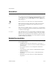
Chapter 1 NI-DNET Software Overview Figure 1-1. NI-DNET Cards Listed in MAX Note Each card’s name uses the word CAN, because the Controller Area Network is the communication protocol upon which DeviceNet is built. If your NI DeviceNet hardware is not listed here, MAX is not configured to search for new devices on startup. To search for the new hardware, press . To verify installation of your DeviceNet hardware, right-click the DeviceNet card, then select Self-test.
Chapter 1 NI-DNET Software Overview Configure DeviceNet Port The physical port of each DeviceNet card is listed under the card’s name. To configure software properties, right-click the port and select Properties. In the Properties dialog, you assign an interface name to the port, such as DNET0 or DNET1. The interface name identifies the physical port within NI-DNET APIs. Change Protocol To change the default protocol for the DeviceNet (CAN) card, right-click the card and select Protocol.
Chapter 1 NI-DNET Software Overview NI-Spy This tool monitors function calls to the NI-DNET APIs. This tool helps in debugging programming problems in your application. To launch this tool, open the Software branch of the MAX Configuration tree, right-click NI Spy, and select Launch NI Spy. SimpleWho To provide valid parameters for the NI-DNET open functions (ncOpenDnetIntf, ncOpenDnetExplMsg, and ncDnetOpenIO), you need to determine some basic information about your DeviceNet devices.
Chapter 1 NI-DNET Software Overview Much like any other object-oriented system, NI-DNET device driver objects use the concepts of class, instance, attribute, and service to describe their features. The NI-DNET device driver software provides three classes of objects: Interface Objects, Explicit Messaging Objects, and I/O Objects. You can open an instance of an NI-DNET object using one of the three open functions (ncOpenDnetExplMsg, ncOpenDnetIntf, or ncOpenDnetIO).
Chapter 1 NI-DNET Software Overview • Execute the DeviceNet Set Attribute Single service on the remote device (ncSetDnetAttribute) • Send any other explicit message request to the remote device and receive the associated explicit message response (ncWriteDnetExplMsg, ncReadDnetExplMsg) • Configure NI-DNET settings that apply to the entire remote device I/O Object The I/O Object represents an I/O connection to a remote DeviceNet device (physical device attached to your interface by a DeviceNet cable)
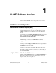
Chapter 1 Access to device at MAC ID 5 I/O Object Device MAC ID = 5 Connection Type = COS NI-DNET Software Overview Access to device at MAC ID 8 I/O Object Device MAC ID = 5 Connection Type = Poll Explicit Messaging Object Device MAC ID = 8 I/O Object Device MAC ID = 8 Connection Type = Strobe Your National Instruments DeviceNet Interface Interface Object Interface MAC ID = 1 Baud Rate = 500K Figure 1-2.
Chapter 1 NI-DNET Software Overview NI-DNET (default), or CAN for NI-CAN. When the CAN protocol is selected, you can access CAN tools in MAX, such as the Bus Monitor tool that displays CAN messages in their raw form. In order to develop NI-CAN applications, you must install NI-CAN components such as documentation and examples. The NI-CAN software components are available within the NI-DNET installer. Launch the setup.
NI-DNET Hardware Overview 2 Types of Hardware The National Instruments DeviceNet hardware includes the PCI-CAN, PXI-8461, and PCMCIA-CAN. The PCI-CAN is software configurable and compliant with the PCI Local Bus Specification. It features the National Instruments MITE bus interface chip that connects the card to the PCI I/O bus. With a PCI-CAN, you can make your PC-compatible computer with PCI Local Bus slots communicate with and control DeviceNet devices.
Chapter 2 NI-DNET Hardware Overview For more information on the DeviceNet physical layer and cables used to connect to your DeviceNet devices, refer to Appendix B, Cabling Requirements. For connection to the network, the PCI-CAN, PXI-8461, and PCMCIA-CAN for DeviceNet provide combicon-style pluggable screw terminals, as required by the DeviceNet Specification. Differences Between CAN Kits and DeviceNet Kits National Instruments provides hardware/software kits for both CAN and DeviceNet.
Developing Your Application 3 This chapter explains how to develop an application using the NI-DNET functions. Accessing NI-DNET from your Programming Environment Applications can access the NI-DNET driver software by using either LabVIEW, LabWindows™/CVI™, Microsoft Visual C/C++, Borland C/C++, or Visual Basic. If you are using any other development environment, you must access the DNET library directly. Each of these language interface techniques is summarized below.
Chapter 3 Developing Your Application LabWindows/CVI Within LabWindows/CVI, the NI-DNET function panel is located in Library»NI-DNET. Like other LabWindows/CVI function panels, the NI-DNET function panel provides help for each function and the ability to generate code. The reference for each NI-DNET function is provided in the NI-DNET Programmer Reference Manual. You can access reference for each function directly from within the function panel. The header file for NI-DNET is nidnet.h.
Chapter 3 Developing Your Application Microsoft C/C++ The NI-DNET software supports Microsoft Visual C/C++ version 6. The header file and library for Visual C/C++ 6 are in the MS Visual C folder of the NI-DNET folder. The typical path to this folder is \Program Files\National Instruments\NI-DNET\MS Visual C. To use NI-DNET, include the nidnet.h header file in your code, then link with the nidnetms.lib library file. For C applications (files with a.
Chapter 3 Developing Your Application For C applications (files with .c extension), include the header file by adding a #include to the beginning of your code, like this: #include "nidnet.h" For C++ applications (files with .cpp extension), define _cplusplus before including the header, such as: #define _cplusplus #include "nidnet.h" The _cplusplus define enables the transition from C++ to the C language NI-DNET functions.
Chapter 3 2. Developing Your Application Get the addresses for the NI-DNET DLL functions you will use. Your application must use the Win32 GetProcAddress function to get the addresses of the NI-DNET functions your application needs. For each NI-DNET function used by your application, you must define a direct entry prototype. For the prototypes for each function exported by nican.dll, refer to the NI-DNET Programmer Reference Manual.
Chapter 3 Developing Your Application 3. Configure your application to de-reference the pointer to call an NI-DNET function, as illustrated by the following code. NCTYPE_STATUS status; NCTYPE_OBJH MyObjh; status = (*PncOpenDnetIO) ("DNET0", &MyObjh); if (status < 0) { printf("ncOpenDnetIO failed"); } 4. Free nican.dll. Before exiting your application, you need to free nican.dll with the following command.
Chapter 3 Developing Your Application Start 1. Open Interface object 2. Open all I/O and Explicit Messaging (EM) objects required for your application 3. Call ncSetDriverAttr, if needed Start communication Your DeviceNet Application: • Write output data • Wait for available input data • Read input data • Get or Set DeviceNet Attribute • Open/Close any new I/O or EM connection if the interface PollMode is not equal to NC_POLL_AUTO Finished? No Yes Stop communication 1. Close I/O and EM objects. 2.
Chapter 3 Developing Your Application Step 1. Open Objects Before you use an NI-DNET object in your application, you must configure and open it using either ncOpenDnetIntf, ncOpenDnetExplMsg, or ncOpenDnetIO. These open functions return a handle for use in all subsequent NI-DNET calls for that object. The ncOpenDnetIntf function configures and opens an Interface Object. Your NI-DNET application uses this Interface Object to start and stop communication.
Chapter 3 Developing Your Application 2. Call the ncWaitForState function with the DesiredState parameter set to Read Available. This function waits for output data to be transmitted and for new input data to be received. If your application is multitasking, you might have other tasks to do in your application while you wait for new input data. If so, use the ncCreateNotification or ncCreateOccurrence function instead of ncWaitForState (refer to Step 2. Start Communication). 3.
Chapter 3 Developing Your Application Step 4. Stop Communication Before you exit your application, stop communication to shut down DeviceNet connections to remote devices. Use the Interface Object to call the ncOperateDnetIntf function with the Opcode parameter set to Stop. Step 5. Close Objects Before you exit your application, close all NI-DNET objects using the ncCloseObject function.
Chapter 3 Developing Your Application If you use two different applications on the same interface and open I/O connections to different devices, you must set PollMode to either Scanned or Individual. You cannot use PollMode of Automatic, because that requires all I/O connections to be open prior to the first start of communication. Checking Status in LabVIEW For applications written in LabVIEW, status checking is handled automatically.
Chapter 3 Developing Your Application Your application code should check the status returned from every NI-DNET function. If an error is detected, you should close all NI-DNET handles, then exit the application. If a warning is detected, you can display a message for debugging purposes, or simply ignore the warning. For more information on status checking, refer to the ncStatusToString function in the NI-DNET Programmer Reference Manual. NI-DNET User Manual 3-12 ni.
NI-DNET Programming Techniques 4 This chapter describes various techniques to help you program your NI-DNET application. The techniques include configuration of I/O connection timing, using I/O data (assemblies), using explicit messaging, and handling multiple devices. Configuring I/O Connections This section provides information on how I/O connections relate to one another and how your configuration of I/O connection timing can affect the overall performance of your DeviceNet system.
Chapter 4 NI-DNET Programming Techniques When you select an ExpPacketRate for an I/O connection, you must consider all I/O connections in your system. For example, although you might be able to configure an ExpPacketRate of 3 ms for a single I/O connection, you cannot configure a 3 ms ExpPacketRate for 40 I/O connections because DeviceNet’s bandwidth capabilities cannot support 40 messages in a 3 ms time frame.
Chapter 4 NI-DNET Programming Techniques Polled I/O Polled I/O connections use a separate poll command and response message for each device. The overall scheme that NI-DNET uses to time polled I/O connections is determined by the PollMode parameter of ncOpenDnetIntf. This PollMode parameter applies to all polled I/O connections (all calls to ncOpenDnetIO with ConnectionType of Poll). The following sections describe different schemes you can use for polled I/O.
Chapter 4 NI-DNET Programming Techniques • If you set the PollMode parameter of ncOpenDnetIntf to Scanned, to configure scanned I/O you must specify the exact same ExpPacketRate when you open each of your strobed/polled I/O connections. Using this scheme, you must determine a valid ExpPacketRate for your DeviceNet system.
Chapter 4 NI-DNET Programming Techniques background polling maintains overall network consistency because NI-DNET evenly disperses all background poll commands among multiple foreground cycles. In other words, all background poll commands are not sent in quick succession and thus do not generate quick bursts of traffic on the network.
Chapter 4 NI-DNET Programming Techniques Since the poll commands are not synchronized for individual polling, they can often be scattered relatively randomly. They can be evenly interspersed for a while, then suddenly occur in bursts of back-to-back messages. Because of this inconsistency, you should use smaller MAC IDs for smaller ExpPacketRate values.
Chapter 4 NI-DNET Programming Techniques Change-of-State (COS) I/O Change-of-State I/O connections use the same timing scheme as cyclic I/O connections, but in addition to the ExpPacketRate, COS I/O sends data to the master whenever a change is detected. For COS I/O, the cyclic transmission is used solely to verify that the I/O connection still exists, so the ExpPacketRate is typically set to a large value, such as 10,000 (10 seconds).
Chapter 4 NI-DNET Programming Techniques For strobed and polled I/O connections, determination of a valid ExpPacketRate can be somewhat complex. If you have trouble estimating an ExpPacketRate value for strobed/polled I/O, set the PollMode parameter of your initial call to ncOpenDnetIntf to Automatic. When you use this automatic EPR feature, the ExpPacketRate parameter of ncOpenDnetIO is ignored for strobed/polled I/O (ConnectionType of Strobe or Poll), and NI-DNET calculates a safe EPR value for you.
Chapter 4 NI-DNET Programming Techniques • Some device vendors provide comments about I/O assemblies in an Electronic Data Sheet (EDS). The EDS file is a text file whose format is defined by the DeviceNet Specification. • Ask the device’s vendor if they have filled out a DeviceNet compliance statement. This form is located at the front of the DeviceNet Specification, and it provides information about the device, including its I/O assemblies.
Chapter 4 NI-DNET Programming Techniques Table 4-1.
Chapter 4 NI-DNET Programming Techniques 4. Right-click on the ByteOffset terminal and select Create Constant, then enter 0 as the byte offset. 5. Right-click on the 8[TF] in terminal and select Create Control. In the front panel control that appears, you can use the button at index 0 to control Run Fwd and the button at index 2 to control Fault Reset. 6. Using the NI-DNET palette, place ncConvertForDnetWrite into your diagram. 7.
Chapter 4 NI-DNET Programming Techniques 2. Initialize the array to all zero. for (I = 0; I < 4; I++) OutputAsm [I] = 0; 3. Assume you have two boolean variables, RunFwd and ResetFault, of type NCTYPE_BOOL. For LabWindows/CVI, these variables could be accessed from front panel buttons. The following code inserts these boolean variables into OutputAsm. if (RunFwd) OutputAsm [0] |= 0x01; if (FaultReset) OutputAsm [0] |= 0x04; 4. Assume you have an integer variable SpeedRef of type NCTYPE_INT16.
Chapter 4 NI-DNET Programming Techniques easiest way to execute the Set Attribute Single service on a remote device is to use the NI-DNET ncSetDnetAttribute function.
Chapter 4 NI-DNET Programming Techniques Specification defines the overall format of these services, in most cases their meaning and service data are object-specific or vendor-specific. Unless your device requires such services and documents them in detail, you probably do not need them for your application.
Chapter 4 NI-DNET Programming Techniques For the C programming language, you can declare a structure typedef to store the parameters of ncOpenDnetIO, similar to the following: typedef struct { NCTYPE_UINT32DeviceMacId; NCTYPE_CONN_TYPEConnectionType; NCTYPE_UINT32InputLength; NCTYPE_UINT32OutputLength; NCTYPE_UINT32ExpPacketRate; } OpenDnetIO_Struct; For LabVIEW, a cluster that contains these parameters is already defined for use with ncOpenDnetIO.
Chapter 4 NI-DNET Programming Techniques Main Loop If your application essentially accesses all DeviceNet input/output data as a single image, you would normally wait for read data to become available on one of the input connections (such as a strobed I/O connection), read all input data, execute your application code, then write all output data. The wait is important because it helps to synchronize your application with the overall DeviceNet network traffic.
DeviceNet Overview A This appendix gives an overview of DeviceNet. History of DeviceNet The Controller Area Network (CAN) was developed in the early 1980s by Bosch, a leading automotive equipment supplier. CAN was developed to overcome the limitations of conventional automotive wiring harnesses. CAN connects devices such as engine controllers, anti-lock brake controllers, and various sensors and actuators on a common serial bus.
Appendix A DeviceNet Overview Physical Characteristics of DeviceNet The following list summarizes the physical characteristics of DeviceNet. • Trunkline-dropline cabling—main trunk cable with a drop cable for each device • Selectable baud rates of 125 K, 250 K, and 500 K Table A-1.
Appendix A 1 2 3 1 Class Square 2 Class Triangle 1 2 DeviceNet Overview 3 4 Class Circle Figure A-1. Classes of Geometric Shapes All squares belong to the same class because they all have similar qualities, such as four equal sides. The term instance refers to a specific instance of a given class. For example, a blue square of four inches per side would be one instance of the class square, and a red square of five inches per side would be another instance.
Appendix A DeviceNet Overview Application Object(s) Parameter Object Assembly Object Identity Object Message Router Explicit Messaging I/O DeviceNet Object Connection Objects DeviceNet Network Figure A-2. Object Modeling Used in DeviceNet Specification Every DeviceNet device contains at least one instance (instance one) of the Identity Object. The Identity Object instance defines attributes which describe the device, including the device’s vendor, product name, and serial number.
Appendix A DeviceNet Overview In Figure A-2, the term Application Object(s) refers to objects within the device which are used to perform its fundamental behavior. For example, within a photoelectric sensor, an instance of the Presence Sensing object (an Application Object) represents the physical photoelectric sensor hardware.
Appendix A DeviceNet Overview The following tables describe the general format of DeviceNet explicit message requests and responses as they appear on the DeviceNet network. Table A-2. Explicit Message Request Field Description Service Code This number identifies the service requested by the client. The DeviceNet Specification defines valid service codes. Class ID This number identifies the class to which the service is directed. The DeviceNet Specification defines valid class IDs.
Appendix A DeviceNet Overview The Get Attribute Single service obtains the value of a specific attribute within a device’s object, and the Set Attribute Single service sets the value of an attribute. These Get and Set services are the most commonly used explicit messaging services. Since these two services are used often, NI-DNET provides functions for these services: ncGetDnetAttribute and ncSetDnetAttribute. Other services defined by DeviceNet are used less often.
Appendix A DeviceNet Overview The DeviceNet Specification defines four types of master/slave I/O connections: polled, bit strobed, change-of-state (COS), and cyclic. A slave device can support at most one polled, one strobed, and one COS or cyclic connection (COS and cyclic connections cannot be used simultaneously). Polled I/O The polled I/O connection uses a request/response scheme for each device. The master sends a poll command (request) message to the slave device with any amount of output data.
Appendix A DeviceNet Overview slave. This strobe command (request) message is received by all slave devices simultaneously and can be used to trigger simultaneous measurements (such as to take multiple photoelectric readings simultaneously). When a strobed slave receives the strobe command, it uses the output data bit that corresponds to its own MAC ID (for example, the slave with MAC ID 5 uses bit 5).
Appendix A DeviceNet Overview The cyclic I/O connection enables a slave device to send input data to its master at the configured EPR interval. You normally configure the EPR to be consistent with the rate at which the device measures its physical input sensors. For example, if a temperature sensor can take a measurement at most once every 500 ms, you would configure the cyclic I/O connection’s EPR as 500 ms.
Appendix A DeviceNet Overview Figure A-5 shows an example of four COS/cyclic I/O connections. Output data Input data Master MAC ID = 1 2 Byte Cyclic to Master EPR = 500 ms, no ACK COS ACK to Slave 4 Byte COS to Master EPR = 200 ms Cyclic ACK to Master 6 Byte COS to Slave EPR = 400 ms, no ACK Slave MAC ID = 9 12 Byte Cyclic to Slave EPR = 100 ms Slave MAC ID = 11 Slave MAC ID = 12 Slave MAC ID = 13 Figure A-5.
Appendix A DeviceNet Overview Instance Instance Attributes Instance Attributes Attributes Output Assembly, Associated with an Output Message Such as a Poll Command Input Assembly, Associated with an Input Message Such as a Poll Response Figure A-6. Input and Output Assemblies As a more specific example, consider a DeviceNet photoelectric sensor (photoeye) or a limit switch. These devices contain a single instance of a class called the Presence Sensing object.
Appendix A DeviceNet Overview As you can see, to use the data bytes contained in I/O messages, it is important to know the format of a device’s internal input and output assemblies. Device Profiles To provide interoperability for devices of the same type, the DeviceNet Specification defines various device profiles.
B Cabling Requirements This appendix describes the cabling requirements for the hardware. Cables should be constructed to meet these requirements as well as the requirements of DeviceNet. DeviceNet cabling requirements can be found in the DeviceNet Specification. Connector Pinouts The PCI-CAN, PXI-8461, and the PCMCIA-CAN bus-powered cable each have a Combicon-style pluggable screw terminal connector. The PCMCIA-CAN bus-powered cable also has a DB-9 D-SUB connector.
Appendix B Cabling Requirements V + S H C _H V C _L Figure B-2 shows the end of a PCMCIA-CAN bus-powered cable. The arrow points to pin 1 of the 5-pin screw terminal block. All of the signals on the 5-pin Combicon-style pluggable screw terminal are connected directly to the corresponding pins on the 9-pin D-SUB following the pinout in Figure B-3. J1 J2 Figure B-2. PCMCIA-CAN Bus-Powered Cable The 9-pin D-SUB follows the pinout recommended by CiA Draft Standard 102.
Appendix B Cabling Requirements Power Supply Information for the DeviceNet Ports The bus must supply power to each DeviceNet port. The bus power supply should be a DC power supply with an output of 10 V to 30 V. The DeviceNet physical layer is powered from the bus using the V+ and V– lines. The power requirements for the DeviceNet port are shown in Table B-1. You should take these requirements into account when determining the requirements of the bus power supply for the system. Table B-1.
Appendix B Cabling Requirements The PCI-CAN is shipped with this jumper set in the EXT position. In this position, the physical layer is powered from the bus (the V+ and V– pins on the Combicon connector). The jumper must be in this position for the DeviceNet interface to be compliant with the DeviceNet Specification. If the DeviceNet interface is being used in a system where bus power is not available, the jumper may be set in the INT position.
Appendix B 3 Cabling Requirements 4 2 1 5 1 2 Power Supply Jumper J6 Power Supply Jumper J5 3 4 Assembly Number Product Name 5 Serial Number Figure B-6. PXI-8461 Parts Locator Diagram Connecting pins 1 and 2 of a jumper configures the PXI-8461 physical layer to be powered externally (from the bus cable power). In this configuration, the power must be supplied on the V+ and V– pins on the port connector.
Appendix B Cabling Requirements Cable Specifications Cables should meet the requirements of the DeviceNet cable specification. DeviceNet cabling requirements can be found in the DeviceNet Specification. Belden cable (3084A) meets all of those requirements and should be suitable for most applications. Cable Lengths The allowable cable length is affected by the characteristics of the cabling and the desired bit transmission rates.
Appendix B Cabling Requirements Cable Termination The pair of signal wires (CAN_H and CAN_L) constitutes a transmission line. If the transmission line is not terminated, each signal change on the line causes reflections that may cause communication failures. Because communication flows both ways on the DeviceNet bus, DeviceNet requires that both ends of the cable be terminated. However, this requirement does not mean that every device should have a termination resistor.
Appendix B Cabling Requirements Cabling Example Figure B-8 shows an example of a cable to connect two DeviceNet devices. 5-Pin Combicon 9-Pin D-Sub Pin 4 Pin 7 Pin 2 Pin 2 Pin 3 Pin 5 Pin 5 Pin 9 Pin 1 Pin 3 CAN_H 120 Ω 9-Pin D-Sub 5-Pin Combicon Pin 7 Pin 4 Pin 2 Pin 2 Pin 5 Pin 3 Pin 9 Pin 5 Pin 3 Pin 1 120 Ω CAN_L GND V+ V– Power Connector V+ V– Figure B-8. Cabling Example NI-DNET User Manual B-8 ni.
Troubleshooting and Common Questions C This appendix describes how to troubleshoot problems with the NI-DNET software and answers some common questions. Troubleshooting with the Measurement & Automation Explorer (MAX) MAX contains configuration information for all CAN (DeviceNet) hardware installed on your system. To start MAX, double-click on the Measurement & Automation icon on your desktop. Your CAN cards are listed in the left pane (Configuration) under Devices and Interfaces.
Appendix C Troubleshooting and Common Questions Troubleshooting Self Test Failures The following topics explain common error messages generated by the Self Test in MAX. Application In Use This error occurs if you are running an application that is using the CAN card. The self test aborts to avoid adversely affecting your application. Before running the self test, exit all applications that use NI-DNET or NI-CAN. If you are using LabVIEW, you may need to exit LabVIEW to unload the NI-DNET driver.
Appendix C Troubleshooting and Common Questions If the error continues after restart, uninstall NI-CAN (and NI-DNET) and then reinstall. NI-CAN Hardware Problem Encountered This error occurs if the Self Test detects a defect in the CAN hardware. If you get this error, write down the numeric code shown with the error and contact National Instruments.
Appendix C Troubleshooting and Common Questions Can I use multiple PCMCIA cards in one computer? Yes, but make sure there are enough free resources available. Unlike PCI or PXI CAN cards, PCMCIA CAN cards cannot share resources, such as IRQs, with other devices. I have problems with my NI PCMCIA CAN card under Windows NT. How can I resolve them? Windows NT offers minimal support for plug and play and there are several things to consider.
D Hardware Specifications This appendix describes the physical characteristics of the DeviceNet hardware, along with the recommended operating conditions. PCI-CAN Series Dimensions............................................. 10.67 by 17.46 cm (4.2 by 6.9 in.) Power requirement ................................. +5 VDC, 775 mA typical I/O connector..........................................
Appendix D Hardware Specifications Storage environment Ambient temperature .......................–20 to 70 °C Relative humidity ............................5 to 90%, noncondensing PXI-CAN Series Dimensions .............................................16.0 by 10.0 cm (6.3 by 3.9 in.) Power requirement..................................+5 VDC, 775 mA typical I/O connector ..........................................
Appendix D Hardware Specifications Port Characteristics Bus power .............................................. 0 to 30 V, 40 mA typical, 100 mA maximum CAN-H, CAN-L..................................... –8 to +18 V, DC or peak, CATI Safety The NI-CAN hardware meets the requirements of the following standards for safety and electrical equipment for measurement, control, and laboratory use: Note • EN 61010-1, IEC 61010-1 • UL 3111-1, UL 61010B-1 • CAN/CSA C22.2 No. 1010.
Appendix D Hardware Specifications CE Compliance This product meets the essential requirements of applicable European Directives, as amended for CE marking, as follows: Low-Voltage Directive (safety)..............73/23/EEC Electromagnetic Compatibility Directive (EMC) .....................................89/336/EEC Refer to the Declaration of Conformity (DoC) for this product for any additional regulatory compliance information. To obtain the DoC for this product, visit ni.com/hardref.
Technical Support and Professional Services E Visit the following sections of the National Instruments Web site at ni.com for technical support and professional services: • Support—Online technical support resources at ni.
Glossary Symbol Prefix Value m milli 10 –3 k kilo 10 3 A A amperes AC alternating current actuator A device that uses electrical, mechanical, or other signals to change the value of an external, real-world variable. In the context of device networks, actuators are devices that receive their primary data value from over the network; examples include valves and motor starters. Also known as final control element.
Glossary B b Bits background polling A polled I/O communication scheme in which all polled slaves are grouped into two different communication rates: a foreground rate and a slower background rate. bit strobed I/O Master/slave I/O connection in which the master broadcasts a single strobe command to all strobed slaves then receives a strobe response from each strobed slave.
Glossary D DC direct current device A physical assembly, linked to a communication line (cable), capable of communicating across the network according to a protocol specification. device network Multi-drop digital communication network for sensors, actuators, and controllers. device profiles DeviceNet specifications which provide interoperability for devices of the same type. direct entry Microsoft Win 32 functions used to directly access the functions of a Dynamic Link Library (DLL).
Glossary H hex Hexadecimal Hz Hertz I I/O connection Connection used for exchange of physical input/output (sensor/activator) data, as well as other control-oriented data. in. inches individual polling A polled I/O communication scheme in which each polled slave communicates at its own individual rate. instance A specific instance of a given class. For example, a blue square of 4 inches per side would be one instance of the class Squares.
Glossary master/slave DeviceNet communication scheme in which a master device allocates connections to one or more slave devices, and those slave devices can only communicate with the master and not one another. MB Megabytes of memory member Individual data value within a DeviceNet I/O Assembly. method See service. multi-drop A physical connection in which multiple devices communicate with one another along a single cable. N network interface A device’s physical connection onto a network.
Glossary P PC personal computer peer-to-peer DeviceNet communication scheme in which each device communicates as a peer and connections are established among devices as needed. PLC Programmable Logic Controller polled I/O Master/slave I/O connection in which the master sends a poll command to a slave, then receives a poll response from that slave. protocol A formal set of conventions or rules for the exchange of information among devices of a given network.
Glossary service An action performed on an instance to affect its behavior; the externally visible code of an object. Within NI-DNET, you use NI-DNET functions to execute services for objects. Also known as method and operation. strobed I/O See bit strobed I/O.
Index C E CE compliance, D-4 change protocol, 1-3 common questions, C-3 and troubleshooting, C-1 components left after NI-CAN software uninstall, C-4 determining NI-CAN software version, C-3 how many CAN interfaces can be configured, C-3 interrupts required for NI-CAN cards, C-3 NI-CAN card and power to CAN bus, C-3 problems with NI PCMCIA CAN card under Windows NT, C-4 troubleshooting with MAX, C-1 using multiple PCMCIA cards, C-4 configure DNET port, 1-3 conventions used in the manual, x conventions, re
Index L R LabVIEW Real-Time (RT) software configuration, 1-3 tools, 1-3 related documentation, x S safety specifications, D-3 self-test failures, troubleshooting, C-2 SimpleWho, 1-4 software LabVIEW Real-Time (RT) tools, 1-3 LabVIEW Real-Time (RT), configuration, 1-3 software (NI resources), E-1 specifications CE compliance, D-4 electromagnetic compatibility, D-3 PCI-CAN series board, D-1 PCMCIA-CAN series card, D-1 safety, D-3 support, technical, E-1 M MAX NI-DNET cards listed in MAX (figure), 1-2 to