PXI NI CardBus-8310-to-PXI Expansion User Manual NI CardBus-8310-to-PXI Expansion User Manual August 2005 371665A-01
Support Worldwide Technical Support and Product Information ni.
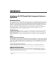
Important Information Warranty The NI CardBus-8310-to-PXI Expansion hardware is warranted against defects in materials and workmanship for a period of one year from the date of shipment, as evidenced by receipts or other documentation. National Instruments will, at its option, repair or replace equipment that proves to be defective during the warranty period. This warranty includes parts and labor.
Compliance Compliance with FCC/Canada Radio Frequency Interference Regulations Determining FCC Class The Federal Communications Commission (FCC) has rules to protect wireless communications from interference. The FCC places digital electronics into two classes. These classes are known as Class A (for use in industrial-commercial locations only) or Class B (for use in residential or commercial locations). All National Instruments (NI) products are FCC Class A products.
Conventions This manual provides information on the installation and use of an NI CardBus-8310-to-PXI Expansion system. The following conventions are used in this manual: » The » symbol leads you through nested menu items and dialog box options to a final action. The sequence File»Page Setup»Options directs you to pull down the File menu, select the Page Setup item, and select Options from the last dialog box. This icon denotes a note, which alerts you to important information.
Contents Chapter 1 Introduction Functional Overview......................................................................................................1-1 Functional Unit Descriptions...........................................................................1-2 CardBus Connector ...........................................................................1-2 StarFabric Bridge ..............................................................................1-2 RJ-45 Connector ...................................
Contents Appendix B Specifications Power Requirements...................................................................................................... B-1 Physical.......................................................................................................................... B-1 Dimensions...................................................................................................... B-2 Operating Environment..............................................................................
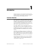
1 Introduction This chapter presents an overview of the hardware functionality of NI CardBus-8310-to-PXI cards, and explains the operation of each functional unit. It also contains recommended steps to be taken while preparing to install the NI CardBus-8310 and NI PXI-8310 modules. Functional Overview The National Instruments CardBus-8310-to-PXI interface kit provides laptop computers direct control of PXI systems.
Chapter 1 Introduction Starfabric Bridge RJ-45 Connector RJ-45 Connector RJ-45 Connector RJ-45 Connector Cardbus-8310 Starfabric Bridge PXI Bus Cardbus Figure 1-1 shows the basic architecture of an NI CardBus-8310-to-PXI system. The NI CardBus-8310 consists of a CardBus connector, a CardBus-to-PXI bridge, a StarFabric bridge and two RJ-45 connectors. The NI PXI-8310 consists of two RJ-45 connectors, a StarFabric bridge, and a PXI connector. PXI-8310 Figure 1-1.
Chapter 1 Introduction RJ-45 Connector This connector is a standard connector commonly used for Ethernet. The StarFabric bridges use the RJ-45 connector with CAT5 cables for a board-to-board interconnect. NI CardBus-8310-to-PXI Cable Options A pair of CAT5-e cables are required to make a complete link: One cable to transmit data and one cable to receive data. You must install these cables in a pair.
Chapter 1 Introduction • Avoid sharp bends or folds in the cables. • Provide enough slack to allow easy device placement. • Avoid things that might cause scuffing and abrasion damage to the cables. • Secure the devices in their shelves using the appropriate hardware. • Use the screws or brackets supplied with the device. Suitable mounting brackets, adapters, and hardware are available from your local computer dealer or retailer. Parts List Table 1-2 lists the components included with your kit.
Chapter 1 Introduction • Handle all sensitive components at an ESD workstation. If possible, use anti-static floor pads and workbench pads. • Handle components and boards with care. Don’t touch the components or contacts on a board. Hold a board by its edges or by its metal mounting bracket. NI PXI-8310 Overview The NI PXI-8310 expansion card is connected to the NI CardBus-8310 through the CAT5-e cables. You must install the PXI card in slot 1 (the system controller slot) of the PXI chassis.
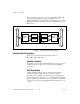
Chapter 1 Introduction If one or more LEDs for a given port (L0 or L1) are not lit, it indicates that the twisted pair represented by that LED is not properly connected. Table 1-3 describes the status indicated by each unlit LED. The same descriptions apply for the L0 LEDs and the L1 LEDs. Table 1-3. Unlit LED Status Descriptions LED Description 0 The PXI card senses no link on its differential pair 0. 1 The PXI card senses no link on its differential pair 1.
Chapter 1 Introduction NI PXI-8310 PXI StarFabric© Interface 1 2 4 3 1 2 L0 Link Status LEDs (0–3) Receiver Ports (RX) 3 4 L1 Link Status LEDs (0–3) Transmitter Ports (TX) Figure 1-2.
2 Hardware and Software Installation The following steps will guide you in completing the installation of your new NI CardBus-8310-to-PXI system. Installation Instructions It is highly recommended that Microsoft Windows users follow the software driver installation instructions exactly, in the order in which the instructions are presented in this chapter. If you do not follow the driver installation instructions, you will greatly increase your chances of failure while configuring your system.
Chapter 2 Hardware and Software Installation Windows 2000/XP (Without XP Service Pack 2) 1. If you do not have your system configured to allow autorun CDs, you must run SETUP.EXE to install the NI CardBus-8310 driver. 2. Follow the prompts to install the software. 3. When the software prompts you reboot, do so. When the system has been rebooted, the installation process is complete. Windows XP (With Service Pack 2) 1.
Chapter 2 Hardware and Software Installation Figure 2-2. Reboot Dialog Box Under Windows XP Service Pack 2 After the reboot, the installation utility will re-launch automatically, and you will see the dialog box shown in Figure. 2-1. 3. Click Next. The dialog box shown in Figure 2-3 will appear. Figure 2-3. Reboot Dialog Box 4. Choose No and click Finish. 5. Manually shut down your computer.
Chapter 2 Hardware and Software Installation Before you shut down the system to proceed to the next step, you should also install any drivers that may be required by the PXI cards. For instance, if you are using a PXI-GPIB card in your expansion chassis, install the latest NI-GPIB driver, etc. Driver CDs are shipped with each PXI card. It is recommended that you install the NI CardBus-8310 driver first, then the PXI drivers.
Chapter 2 3. Hardware and Software Installation For each cable, Receive (RX) on one card attaches to Transmit (TX) on the other card. Attach one CAT5-e cable to the Receive (RX) port on the NI CardBus-8310 card. Attach the other end to the Transmit (TX) terminal on the NI PXI-8310 card. Attach one CAT5-e cable to the Transmit (TX) port on the NI CardBus-8310 card, then attach the other end to the Receive (RX) port on the NI PXI-8310 card.
Chapter 2 Hardware and Software Installation 1. Make sure your CAT5-e cables are connected correctly, then turn on the PXI chassis, and plug the NI CardBus-8310 card into the laptop. Power up the host computer. 2. Both LEDs should be lit on the NI PXI-8310. Flashing LEDs indicate that the wires are reversed. If the LEDs are flashing, switch the wires and begin again at step 1. 3. The dialog box shown in Figure 2-4 will appear the first time you boot your computer with the PXI chassis connected.
Chapter 2 Hardware and Software Installation Figure 2-5. Software Installation Options 5. Choose automatic installation and click Next. Figure 2-6. Installation Wizard Completion Dialog Box 6. © National Instruments Corporation Once the StarGen PCI to PCI bridge installation is complete, click Finish.
Chapter 2 Hardware and Software Installation 7. The Found New Hardware Wizard dialog box will appear again, and will find another PCI to PCI bridge, because there are two bridge chips. Follow the instructions outlined in steps 4 through 7 to successfully install the second PCI to PCI bridge. 8. The Found New Hardware Wizard will now detect the PXI modules that have been installed in the PXI chassis. Follow the same procedure described in steps 4 through 7 to successfully install each module.
Chapter 2 Hardware and Software Installation Figure 2-7. PXI Module Shown In Device Manager Tree The NI CardBus-8310 CardBus Driver installation is now complete. Powering Down The hardware will not support powering down the chassis before the host computer. If you do so, the machine may hang, blue screen, or it may even appear to be working. The condition of the system will be very unstable.
Chapter 2 Hardware and Software Installation Running the System Cautions High voltages are present inside the chassis when the chassis power cord is plugged into an electrical outlet. Disconnect the power cord from its source. Before touching anything inside the chassis, move to an ESD station and follow proper ESD procedure. Failure to do so may result in electrostatic discharge damaging the computer or its components.
Chapter 2 Hardware and Software Installation Figure 2-8. Star Configuration (Preferred) Figure 2-9. Daisy-Chain Configuration (Non-Preferred) System Boot In systems with a large number of modules and chassis, the host computer may appear to hang, taking more than 20 seconds at the Windows XP splash screen. This operation is expected, as the operating system is enumerating all the devices in the PCI bus hierarchy, which can take time in a complex configuration.
A PCIScope Overview PCIScope is a powerful monitoring tool designed by the German company APSoft. This software utility is used to explore, examine and debug the PCI subsystem of your computer. PCIScope has proven to be very useful when verifying and debugging configurations involving an NI PXI expansion system under a Windows platform.
Appendix A PCIScope Figure A-1. Example of PCIScope Interface The data can be stored as a *.bpd file on your computer. You may be requested to email this file to support@ni.com if you are experiencing configuration problems. NI CardBus-8310-to-PXI Expansion User Manual A-2 ni.
B Specifications This appendix deals with safety and environmental specifications for the NI CardBus-8310-to-PXI Expansion system. Power Requirements This section discusses the DC output for the NI CardBus-8310-to-PXI system. NI CardBus-8310 Typical 3.3 V ........................................ 0.25 A 5 V ........................................... 0 A Maximum 3.3 V ........................................ 0.30 A 5 V ........................................... 0 A NI PXI-8310 Typical 3.3 V .............
Appendix B Specifications Dimensions NI CardBus-8310....................................Type II PC Card NI PXI-8310 ...........................................1-slot 3U PXI module Slot requirements ....................................One 3U PXI system controller slot Maximum cable length ...........................14 m Compatibility ..........................................Fully compatible with the PXI Hardware Specification 2.1 Operating Environment Temperature CardBus-8310.............................
Appendix B Specifications Electromagnetic Compatibility Emissions ............................................... EN 55011 Class A @ 10 meters FCC Part 15A above 1 GHz Immunity................................................ Evaluated to EN 61326:1998, Table 1 EMC/EMI............................................... CE, C-Tick, and FCC Part 15 (Class A) Compliant CE Compliance Refer to the Declaration of Conformity (DoC) for this product for any additional regulatory compliance information.
C Troubleshooting NI PXI-CardBus-8310 Cards This appendix deals with troubleshooting methods for an NI CardBus-8310-to-PXI system. To avoid potential issues with this configuration, please install the NI CardBus-8310 driver before inserting the CardBus card.
Appendix C Troubleshooting NI PXI-CardBus-8310 Cards Troubleshooting The following list relates problems that have been observed during initialization. Below the list, elaboration upon each issue is provided, along with steps to correct it. 1. No LEDs are lit on the NI PXI-8310 card. 2. The LEDs are flashing on the NI PXI-8310 card. 3. One or more LEDs are not lit on the NI PXI-8310 card. 4. An error is returned after inserting the CardBus card before installing the CardBus card driver. 5.
Appendix C Troubleshooting NI PXI-CardBus-8310 Cards • Try ejecting and re-inserting the CardBus card. • Power down the laptop and the chassis system. Power up the chassis first and then power up the computer. Issue: One or more LEDs are not lit on the NI PXI-8310 card. This may be a defective hardware. Please call customer service for support. Note The hardware may still appear to function, but at a reduced bandwidth.
Appendix C Troubleshooting NI PXI-CardBus-8310 Cards Issue: The host computer is unable to detect the PXI chassis. • • • If the LEDs are flashing on the NI PXI-8310 card: – Try ejecting and reinserting the CardBus card. – Power down the laptop and the chassis system. Power up the chassis first and then the computer. If there are no LEDs lit on the NI PXI-8310 card: – Verify that the CardBus card is inserted properly. – Try ejecting and re-inserting the CardBus card.
Appendix C Troubleshooting NI PXI-CardBus-8310 Cards Issue: The application or program is unable to detect the third party PXI card. Go to Windows Device Manager»View»Devices by connection, expand the device branches to see if there is a yellow exclamation mark (error) in front of the affected PXI card. • If there is a yellow exclamation mark in front of the PXI card: – Double-click on the PXI device to find out the Error Code number.
Appendix C Troubleshooting NI PXI-CardBus-8310 Cards Issue: The host computer is blue-screening/frozen while installing the NI CardBus-8310 driver. Re-install the NI CardBus-8310 driver again from the driver CD provided in your kit. If the problem occurs consistently, please contact National Instruments for technical support. Issue: The system froze after installing the NI CardBus-8310 driver.
Appendix C Troubleshooting NI PXI-CardBus-8310 Cards If the problem occurs consistently, please contact National Instruments for technical support. Issue: The application or program failed to communicate with the PXI device card during an operation. • Make sure the PXI chassis is properly powered. • Check the LED lights on the NI PXI-8310 card. – – – No LEDs lit on the NI PXI-8310 card. • Re-insert the NI CardBus-8310 card. • Re-seat both cable connections.
Appendix C Troubleshooting NI PXI-CardBus-8310 Cards • If another card that has worked in the past is available, try it in the same slot. • Plug the card into a different slot in the chassis, to ensure that the chassis is functional. Error Code (Yellow Exclamation Mark) in Device Manager The following section interprets the error codes corresponding to the yellow exclamation point used in Windows Device Manager to denote hardware errors.
Appendix C Troubleshooting NI PXI-CardBus-8310 Cards NI icon in the system tray of your desktop, click Reset Bridges Settings and restart your computer. Error Code 28 on the Other PCI Bridge Device This code means the device was not installed completely. Re-install the NI CardBus-8310 driver from the driver CD provided before inserting the NI CardBus-8310 card into the CardBus slot of the host computer.
Technical Support and Professional Services D Visit the following sections of the National Instruments Web site at ni.com for technical support and professional services: • Support—Online technical support resources at ni.
Appendix D Technical Support and Professional Services • Declaration of Conformity (DoC)—A DoC is our claim of compliance with the Council of the European Communities using the manufacturer’s declaration of conformity. This system affords the user protection for electronic compatibility (EMC) and product safety. You can obtain the DoC for your product by visiting ni.com/certification. A PDF copy of the DOC is available on the NI-PXI-CardBus-8310 driver CD. If you searched ni.
Index C I cable installation, 2-4 cable options, 1-3 CardBus-8310 installation, 2-5 contacting technical support, C-1 conventions used in the manual, v Declaration of Conformity (NI resources), D-2 diagnostic tools (NI resources), D-1 documentation conventions used in the manual, v NI resources, D-1 drivers (NI resources), D-1 installation cabling, 2-4 CardBus-8310, 2-5 ESD protection, 1-4 parts list, 1-4 powering up, 2-5 preparation, 1-3 PXI cards, 2-4 software driver, 2-1 supported operating systems,
Index N specifications electromagnetic compatibility, B-3 safety, B-2 StarFabric bridge, 1-2 supported operating systems, 2-1 system boot latencies, 2-11 system hierarchy, 2-10 system operation, 2-10 National Instruments support and services, D-1 NI CardBus-8310, 1-2 NI PXI-8310, 1-5 front view (figure), 1-7 NI support and services, D-1 O T OS support, 2-1 overview cabling, 1-3 functional, 1-1 NI CardBus-8310, 1-2 NI PXI-8310, 1-5 RJ-45 connector, 1-3 StarFabric bridge, 1-2 technical support, D-1 tra