
Computer Accessories User Manual

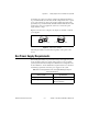
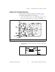
Table Of Contents
- Getting Started with Your PXI-8461 or PXI-8460 and the NI-CAN™ Software for Windows NT
- Support
- Important Information
- Compliance
- Contents
- About This Manual
- Chapter 1 Introduction
- Chapter 2 Installation and Configuration
- Chapter 3 Verify the Installation
- Chapter 4 Begin to Use the NI-CAN Software
- Appendix A Uninstalling the Hardware and Software
- Appendix B Cabling Requirements for PXI-8461 High-Speed CAN
- Appendix C Cabling Requirements for PXI-8460 Low-Speed CAN
- Appendix D Troubleshooting and Common Questions
- Appendix E Specifications
- Appendix F Technical Support Resources
- Glossary
- Figures
- Figure 2-1. Add/Remove Programs Properties Dialog Box
- Figure 2-2. Installing the PXI Hardware
- Figure 2-3. PXI-8461 That Is Working Properly
- Figure 2-4. NI-CAN Hardware Settings Dialog Box
- Figure 3-1. NI CAN Diagnostic Utility after Testing
- Figure A-1. Add/Remove Programs Properties Dialog Box
- Figure B-1. Pinout for 9-Pin D-Sub Connector
- Figure B-2. Pinout for 5-Pin Combicon-Style Pluggable Screw Terminal
- Figure B-3. PXI-8461 Part Locator Diagram
- Figure B-4. Power Source Jumpers
- Figure B-5. Termination Resistor Placement
- Figure B-6. Cabling Example
- Figure C-1. Pinout for 9-Pin D-Sub Connector
- Figure C-2. PXI-8460 Parts Locator Diagram
- Figure C-3. Power Source Jumpers
- Figure C-4. Termination Resistor Placement for Low-Speed CAN
- Figure C-5. Location of Termination Resistors on a PXI-8460
- Figure C-6. Preparing Lead Wires of Replacement Resistors
- Figure C-7. Cabling Example
- Tables
- Table B-1. Power Requirements for the CAN Physical Layer for Bus-Powered Versions
- Table B-2. ISO 11898 Specifications for Characteristics of a CAN_H and CAN_L Pair of Wires
- Table B-3. DeviceNet Cable Length Specifications
- Table C-1. Power Requirements for the Low-Speed CAN Physical Layer for Bus-Powered Versions
- Table C-2. ISO 11519-2 Specifications for Characteristics of a CAN_H and CAN_L Pair of Wires
Appendix C Cabling Requirements for PXI-8460 Low-Speed CAN
PXI-8461 or PXI-8460 and NI-CAN for Windows NT C-6 www.natinst.com
Philips also recommends an individual device RTH and RTL termination of
500 Ω to 16 kΩ. The PXI-8460 board ships with mounted RTH and RTL
values of 510 Ω ±5% per port. The PXI-8460 kit also includes a pair of
15 kΩ ±5% resistors for each port. After determining the termination of
your existing network or device, you can use the following formula to
indicate which value should be placed on your PXI-8460 board in order to
produce the proper overall RTH and RTL termination of 100 to 500 Ω upon
connection of the board:
*R
RTH overall
should be between 100 and 500 Ω
**R
RTH of low-speed CAN interface
= 510 Ω ±5% (mounted) or 15 kΩ ±5% (in kit)
†R
RTH
= R
RTL
As the formula indicates, the 510 Ω ±5% shipped on your board will work
with properly terminated networks having a total RTH and RTL
termination of 125 to 500 Ω, or individual devices having an RTH and RTL
termination of 500 Ω to 16 kΩ. For communication with a network having
an overall RTH and RTL termination of 100 to 125 Ω, you will need to
replace the 510 Ω resistors with the 15 kΩ resistors in the kit. Please refer
to the next section, Replacing the Termination Resistors.
R
RTH overall*
†
1
1
R
RTH of low-speed CAN interface**
-----------------------------------------------------------------
1
R
RTH of existing network or device
--------------------------------------------------------------+
-------------------------------------------------------------------------------------------------------------------------------------------=