
Computer Accessories User Manual
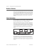
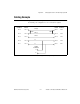
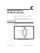

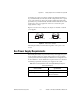
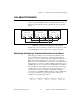
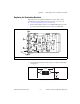
Table Of Contents
- Getting Started with Your PXI-8461 or PXI-8460 and the NI-CAN™ Software for Windows NT
- Support
- Important Information
- Compliance
- Contents
- About This Manual
- Chapter 1 Introduction
- Chapter 2 Installation and Configuration
- Chapter 3 Verify the Installation
- Chapter 4 Begin to Use the NI-CAN Software
- Appendix A Uninstalling the Hardware and Software
- Appendix B Cabling Requirements for PXI-8461 High-Speed CAN
- Appendix C Cabling Requirements for PXI-8460 Low-Speed CAN
- Appendix D Troubleshooting and Common Questions
- Appendix E Specifications
- Appendix F Technical Support Resources
- Glossary
- Figures
- Figure 2-1. Add/Remove Programs Properties Dialog Box
- Figure 2-2. Installing the PXI Hardware
- Figure 2-3. PXI-8461 That Is Working Properly
- Figure 2-4. NI-CAN Hardware Settings Dialog Box
- Figure 3-1. NI CAN Diagnostic Utility after Testing
- Figure A-1. Add/Remove Programs Properties Dialog Box
- Figure B-1. Pinout for 9-Pin D-Sub Connector
- Figure B-2. Pinout for 5-Pin Combicon-Style Pluggable Screw Terminal
- Figure B-3. PXI-8461 Part Locator Diagram
- Figure B-4. Power Source Jumpers
- Figure B-5. Termination Resistor Placement
- Figure B-6. Cabling Example
- Figure C-1. Pinout for 9-Pin D-Sub Connector
- Figure C-2. PXI-8460 Parts Locator Diagram
- Figure C-3. Power Source Jumpers
- Figure C-4. Termination Resistor Placement for Low-Speed CAN
- Figure C-5. Location of Termination Resistors on a PXI-8460
- Figure C-6. Preparing Lead Wires of Replacement Resistors
- Figure C-7. Cabling Example
- Tables
- Table B-1. Power Requirements for the CAN Physical Layer for Bus-Powered Versions
- Table B-2. ISO 11898 Specifications for Characteristics of a CAN_H and CAN_L Pair of Wires
- Table B-3. DeviceNet Cable Length Specifications
- Table C-1. Power Requirements for the Low-Speed CAN Physical Layer for Bus-Powered Versions
- Table C-2. ISO 11519-2 Specifications for Characteristics of a CAN_H and CAN_L Pair of Wires
Appendix C Cabling Requirements for PXI-8460 Low-Speed CAN
© National Instruments Corporation C-5 PXI-8461 or PXI-8460 and NI-CAN for Windows NT
Low-Speed Termination
Every device on the low-speed CAN network requires a termination
resistor for each CAN data line: R
RTH
for CAN_H and R
RTL
for CAN_L.
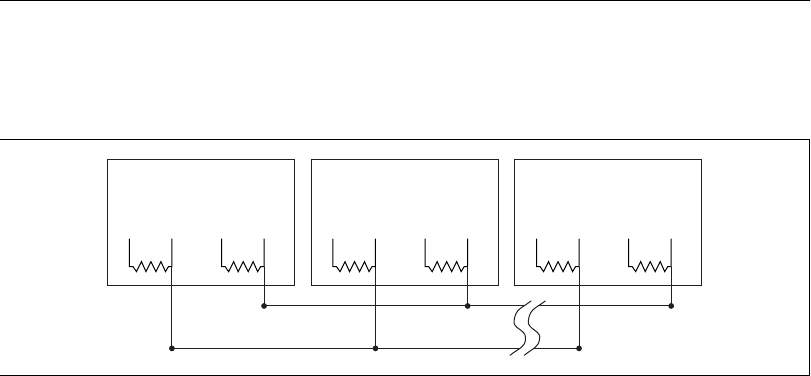
Figure C-4 shows termination resistor placement in a low-speed CAN
network.
Figure C-4.
Termination Resistor Placement for Low-Speed CAN
The following sections explain how to determine the correct resistor values
for your PXI-8460, and how to replace those resistors, if necessary.
Determining the Necessary Termination Resistance for Your Board
Unlike high-speed CAN, low-speed CAN requires termination at the
low-speed CAN transceiver instead of on the cable. The termination
requires one resistor for each CAN line. This configuration allows the
Philips fault-tolerant CAN transceiver to detect any of seven network
faults. You can use your PXI-8460 to connect to a low-speed CAN network
having from two to 32 nodes as specified by Philips (including the port on
the PXI-8460 as a node). You can also use the PXI-8460 to communicate
with individual low-speed CAN devices. It is important to determine the
overall termination of your existing network, or the termination of your
individual device, before connecting it to a PXI-8460 port. Philips
recommends an overall RTH and RTL termination of 100 to 500 Ω (each)
for a properly terminated low-speed network. The overall network
termination may be determined as follows:
Low-speed
CAN Device
RTL CAN_L RTH CAN_H
Low-speed
CAN Device
RTL CAN_L RTH CAN_H
Low-speed
CAN Device
RTL CAN_L RTH CAN_H
CAN_H
CAN_L
1
R
RTH overall
†
--------------------------
1
R
RTH node 1
------------------------
1
R
RTH node 2
------------------------
1
R
RTH node 3
------------------------
1
R
RTH or node n...
--------------------------------+++=