
Computer Accessories User Manual
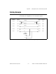
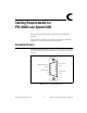

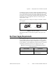
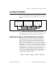
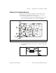
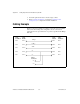
Table Of Contents
- Getting Started with Your PXI-8461 or PXI-8460 and the NI-CAN™ Software for Windows NT
- Support
- Important Information
- Compliance
- Contents
- About This Manual
- Chapter 1 Introduction
- Chapter 2 Installation and Configuration
- Chapter 3 Verify the Installation
- Chapter 4 Begin to Use the NI-CAN Software
- Appendix A Uninstalling the Hardware and Software
- Appendix B Cabling Requirements for PXI-8461 High-Speed CAN
- Appendix C Cabling Requirements for PXI-8460 Low-Speed CAN
- Appendix D Troubleshooting and Common Questions
- Appendix E Specifications
- Appendix F Technical Support Resources
- Glossary
- Figures
- Figure 2-1. Add/Remove Programs Properties Dialog Box
- Figure 2-2. Installing the PXI Hardware
- Figure 2-3. PXI-8461 That Is Working Properly
- Figure 2-4. NI-CAN Hardware Settings Dialog Box
- Figure 3-1. NI CAN Diagnostic Utility after Testing
- Figure A-1. Add/Remove Programs Properties Dialog Box
- Figure B-1. Pinout for 9-Pin D-Sub Connector
- Figure B-2. Pinout for 5-Pin Combicon-Style Pluggable Screw Terminal
- Figure B-3. PXI-8461 Part Locator Diagram
- Figure B-4. Power Source Jumpers
- Figure B-5. Termination Resistor Placement
- Figure B-6. Cabling Example
- Figure C-1. Pinout for 9-Pin D-Sub Connector
- Figure C-2. PXI-8460 Parts Locator Diagram
- Figure C-3. Power Source Jumpers
- Figure C-4. Termination Resistor Placement for Low-Speed CAN
- Figure C-5. Location of Termination Resistors on a PXI-8460
- Figure C-6. Preparing Lead Wires of Replacement Resistors
- Figure C-7. Cabling Example
- Tables
- Table B-1. Power Requirements for the CAN Physical Layer for Bus-Powered Versions
- Table B-2. ISO 11898 Specifications for Characteristics of a CAN_H and CAN_L Pair of Wires
- Table B-3. DeviceNet Cable Length Specifications
- Table C-1. Power Requirements for the Low-Speed CAN Physical Layer for Bus-Powered Versions
- Table C-2. ISO 11519-2 Specifications for Characteristics of a CAN_H and CAN_L Pair of Wires
Appendix C Cabling Requirements for PXI-8460 Low-Speed CAN
© National Instruments Corporation C-3 PXI-8461 or PXI-8460 and NI-CAN for Windows NT
Connecting pins 2 and 3 of a jumper configures the CAN physical layer to
be powered internally (from the card). In this configuration, the V– signal
serves as the reference ground for the isolated signals. Even if the CAN
physical layer is powered internally, the fault-tolerant CAN transceiver still
requires bus power to be supplied in order for it to monitor the power
supply (battery) voltage.
Figure C-3 shows how to configure your jumpers for internal or external
power supplies.
Figure C-3. Power Source Jumpers
The CAN physical layer is still isolated regardless of the power source
chosen.
Bus Power Supply Requirements
If the CAN physical layer is powered from a bus power supply, the power
supply should be a DC power supply with an output of 8 V to 27V. The
power requirements for the CAN ports for Bus-Powered configurations are
shown in Table C-1. You should take these requirements into account when
determining requirements of the bus power supply for the system.
Table C-1. Power Requirements for the Low-Speed CAN Physical Layer for
Bus-Powered Versions
Characteristic Specification
Voltage requirement V+ 8–27 VDC
Current requirement 40 mA typical
100 mA maximum
INT EXT
a. Internal Power Mode
INT EXT
b. External Power Mode
123123