
Computer Accessories User Manual
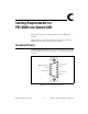

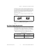
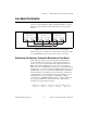
Table Of Contents
- Getting Started with Your PXI-8461 or PXI-8460 and the NI-CAN™ Software for Windows NT
- Support
- Important Information
- Compliance
- Contents
- About This Manual
- Chapter 1 Introduction
- Chapter 2 Installation and Configuration
- Chapter 3 Verify the Installation
- Chapter 4 Begin to Use the NI-CAN Software
- Appendix A Uninstalling the Hardware and Software
- Appendix B Cabling Requirements for PXI-8461 High-Speed CAN
- Appendix C Cabling Requirements for PXI-8460 Low-Speed CAN
- Appendix D Troubleshooting and Common Questions
- Appendix E Specifications
- Appendix F Technical Support Resources
- Glossary
- Figures
- Figure 2-1. Add/Remove Programs Properties Dialog Box
- Figure 2-2. Installing the PXI Hardware
- Figure 2-3. PXI-8461 That Is Working Properly
- Figure 2-4. NI-CAN Hardware Settings Dialog Box
- Figure 3-1. NI CAN Diagnostic Utility after Testing
- Figure A-1. Add/Remove Programs Properties Dialog Box
- Figure B-1. Pinout for 9-Pin D-Sub Connector
- Figure B-2. Pinout for 5-Pin Combicon-Style Pluggable Screw Terminal
- Figure B-3. PXI-8461 Part Locator Diagram
- Figure B-4. Power Source Jumpers
- Figure B-5. Termination Resistor Placement
- Figure B-6. Cabling Example
- Figure C-1. Pinout for 9-Pin D-Sub Connector
- Figure C-2. PXI-8460 Parts Locator Diagram
- Figure C-3. Power Source Jumpers
- Figure C-4. Termination Resistor Placement for Low-Speed CAN
- Figure C-5. Location of Termination Resistors on a PXI-8460
- Figure C-6. Preparing Lead Wires of Replacement Resistors
- Figure C-7. Cabling Example
- Tables
- Table B-1. Power Requirements for the CAN Physical Layer for Bus-Powered Versions
- Table B-2. ISO 11898 Specifications for Characteristics of a CAN_H and CAN_L Pair of Wires
- Table B-3. DeviceNet Cable Length Specifications
- Table C-1. Power Requirements for the Low-Speed CAN Physical Layer for Bus-Powered Versions
- Table C-2. ISO 11519-2 Specifications for Characteristics of a CAN_H and CAN_L Pair of Wires
Appendix B Cabling Requirements for PXI-8461 High-Speed CAN
PXI-8461 or PXI-8460 and NI-CAN for Windows NT B-6 www.natinst.com
Number of Devices
The maximum number of devices that you can connect to a CAN port
depends on the electrical characteristics of the devices on the network. If all
of the devices meet the requirements of ISO 11898, at least 30 devices may
be connected to the bus. Higher numbers of devices may be connected if the
electrical characteristics of the devices do not degrade signal quality below
ISO 11898 signal level specifications. If all of the devices on the network
meet the DeviceNet specifications, 64 devices may be connected to the
network.
Cable Termination
The pair of signal wires (CAN_H and CAN_L) constitutes a transmission
line. If the transmission line is not terminated, each signal change on the
line causes reflections that may cause communication failures.
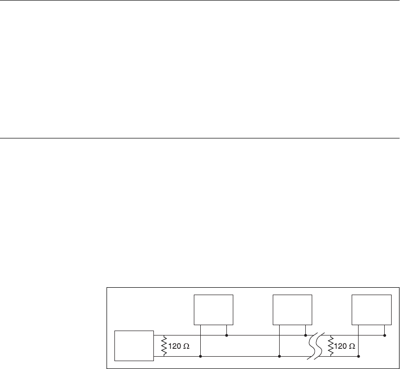
Because communication flows both ways on the CAN bus, CAN requires
that both ends of the cable be terminated. However, this requirement does
not mean that every device should have a termination resistor. If multiple
devices are placed along the cable, only the devices on the ends of the cable
should have termination resistors. See Figure B-5 for an example of where
termination resistors should be placed in a system with more than two
devices.
Figure B-5.
Termination Resistor Placement
The termination resistors on a cable should match the nominal impedance
of the cable. ISO 11898 requires a cable with a nominal impedance of
120 Ω; therefore, a 120
Ω resistor should be used at each end of the cable.
Each termination resistor should be capable of dissipating at least 0.25 W
of power.
CAN
Device
CAN
Device
CAN
Device
CAN
Device
CAN_L
CAN_H