
Computer Accessories User Manual
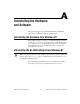
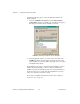

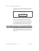

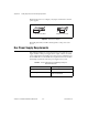
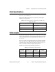
Table Of Contents
- Getting Started with Your PXI-8461 or PXI-8460 and the NI-CAN™ Software for Windows NT
- Support
- Important Information
- Compliance
- Contents
- About This Manual
- Chapter 1 Introduction
- Chapter 2 Installation and Configuration
- Chapter 3 Verify the Installation
- Chapter 4 Begin to Use the NI-CAN Software
- Appendix A Uninstalling the Hardware and Software
- Appendix B Cabling Requirements for PXI-8461 High-Speed CAN
- Appendix C Cabling Requirements for PXI-8460 Low-Speed CAN
- Appendix D Troubleshooting and Common Questions
- Appendix E Specifications
- Appendix F Technical Support Resources
- Glossary
- Figures
- Figure 2-1. Add/Remove Programs Properties Dialog Box
- Figure 2-2. Installing the PXI Hardware
- Figure 2-3. PXI-8461 That Is Working Properly
- Figure 2-4. NI-CAN Hardware Settings Dialog Box
- Figure 3-1. NI CAN Diagnostic Utility after Testing
- Figure A-1. Add/Remove Programs Properties Dialog Box
- Figure B-1. Pinout for 9-Pin D-Sub Connector
- Figure B-2. Pinout for 5-Pin Combicon-Style Pluggable Screw Terminal
- Figure B-3. PXI-8461 Part Locator Diagram
- Figure B-4. Power Source Jumpers
- Figure B-5. Termination Resistor Placement
- Figure B-6. Cabling Example
- Figure C-1. Pinout for 9-Pin D-Sub Connector
- Figure C-2. PXI-8460 Parts Locator Diagram
- Figure C-3. Power Source Jumpers
- Figure C-4. Termination Resistor Placement for Low-Speed CAN
- Figure C-5. Location of Termination Resistors on a PXI-8460
- Figure C-6. Preparing Lead Wires of Replacement Resistors
- Figure C-7. Cabling Example
- Tables
- Table B-1. Power Requirements for the CAN Physical Layer for Bus-Powered Versions
- Table B-2. ISO 11898 Specifications for Characteristics of a CAN_H and CAN_L Pair of Wires
- Table B-3. DeviceNet Cable Length Specifications
- Table C-1. Power Requirements for the Low-Speed CAN Physical Layer for Bus-Powered Versions
- Table C-2. ISO 11519-2 Specifications for Characteristics of a CAN_H and CAN_L Pair of Wires
Appendix B Cabling Requirements for PXI-8461 High-Speed CAN
PXI-8461 or PXI-8460 and NI-CAN for Windows NT B-4 www.natinst.com
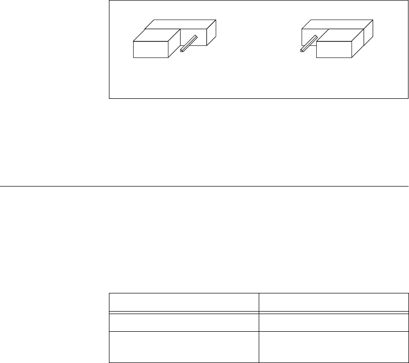
Figure B-4 shows how to configure your jumpers for internal or external
power supplies.
Figure B-4. Power Source Jumpers
The CAN physical layer is still isolated regardless of the power source
chosen.
Bus Power Supply Requirements
If the CAN physical layer is powered from a bus power supply, the power
supply should be a DC power supply with an output of 10 V to 30 V. The
power requirements for the CAN ports for bus-powered configurations are
shown in Table B-1. You should take these requirements into account when
determining requirements of the bus power supply for the system.
Table B-1. Power Requirements for the CAN Physical Layer for
Bus-Powered Versions
Characteristic Specification
Voltage requirement V+ 10 to 30 VDC
Current requirement 40 mA typical
100 mA maximum
INT EXT
a. Internal Power Mode
INT EXT
b. External Power Mode
123123