
Computer Accessories User Manual
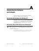
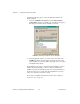

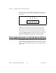

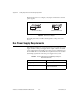
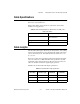
Table Of Contents
- Getting Started with Your PXI-8461 or PXI-8460 and the NI-CAN™ Software for Windows NT
- Support
- Important Information
- Compliance
- Contents
- About This Manual
- Chapter 1 Introduction
- Chapter 2 Installation and Configuration
- Chapter 3 Verify the Installation
- Chapter 4 Begin to Use the NI-CAN Software
- Appendix A Uninstalling the Hardware and Software
- Appendix B Cabling Requirements for PXI-8461 High-Speed CAN
- Appendix C Cabling Requirements for PXI-8460 Low-Speed CAN
- Appendix D Troubleshooting and Common Questions
- Appendix E Specifications
- Appendix F Technical Support Resources
- Glossary
- Figures
- Figure 2-1. Add/Remove Programs Properties Dialog Box
- Figure 2-2. Installing the PXI Hardware
- Figure 2-3. PXI-8461 That Is Working Properly
- Figure 2-4. NI-CAN Hardware Settings Dialog Box
- Figure 3-1. NI CAN Diagnostic Utility after Testing
- Figure A-1. Add/Remove Programs Properties Dialog Box
- Figure B-1. Pinout for 9-Pin D-Sub Connector
- Figure B-2. Pinout for 5-Pin Combicon-Style Pluggable Screw Terminal
- Figure B-3. PXI-8461 Part Locator Diagram
- Figure B-4. Power Source Jumpers
- Figure B-5. Termination Resistor Placement
- Figure B-6. Cabling Example
- Figure C-1. Pinout for 9-Pin D-Sub Connector
- Figure C-2. PXI-8460 Parts Locator Diagram
- Figure C-3. Power Source Jumpers
- Figure C-4. Termination Resistor Placement for Low-Speed CAN
- Figure C-5. Location of Termination Resistors on a PXI-8460
- Figure C-6. Preparing Lead Wires of Replacement Resistors
- Figure C-7. Cabling Example
- Tables
- Table B-1. Power Requirements for the CAN Physical Layer for Bus-Powered Versions
- Table B-2. ISO 11898 Specifications for Characteristics of a CAN_H and CAN_L Pair of Wires
- Table B-3. DeviceNet Cable Length Specifications
- Table C-1. Power Requirements for the Low-Speed CAN Physical Layer for Bus-Powered Versions
- Table C-2. ISO 11519-2 Specifications for Characteristics of a CAN_H and CAN_L Pair of Wires
Appendix B Cabling Requirements for PXI-8461 High-Speed CAN
PXI-8461 or PXI-8460 and NI-CAN for Windows NT B-2 www.natinst.com
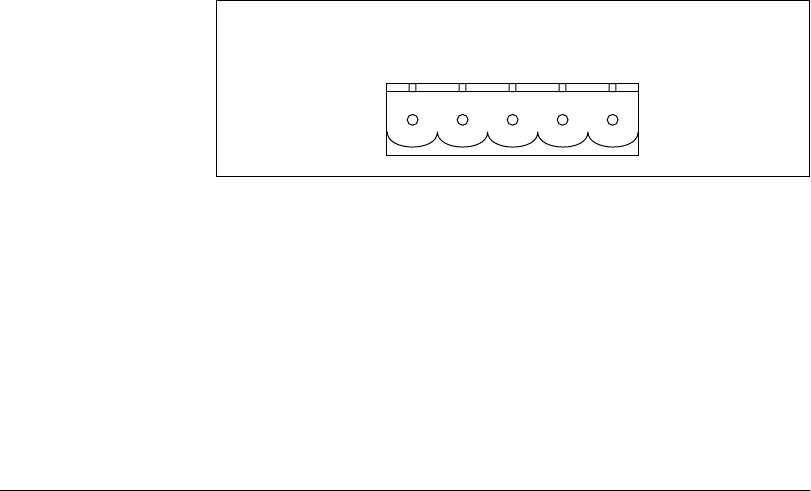
The 5-pin Combicon-style pluggable screw terminal follows the pinout
required by the DeviceNet Specification. Figure B-2 shows the pinout for
this connector.
Figure B-2. Pinout for 5-Pin Combicon-Style Pluggable Screw Terminal
CAN_H and CAN_L are signal lines that carry the data on the CAN
network. These signals should be connected using twisted-pair cable.
The V+ and V– pins are used to supply bus power to the CAN physical
layer if external power is required for the CAN physical layer. If internal
power for the CAN physical layer is used, the V– pin serves as the reference
ground for CAN_H and CAN_L. See the next section, Power Supply
Information for the High-Speed CAN Ports, for more information.
Power Supply Information for the High-Speed CAN Ports
For the PXI-8461, a jumper controls the source of power for the CAN
physical layer. For the one-port boards and port one of the two-port boards,
power is configured with jumper J5. For port two of the two-port boards,
power is configured with jumper J6. The location of these jumpers is shown
in Figure B-3.
CAN_L
V–
CAN_H
V+
Shield
12345