
Computer Accessories User Manual
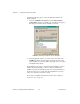


Table Of Contents
- Getting Started with Your PXI-8461 or PXI-8460 and the NI-CAN™ Software for Windows NT
- Support
- Important Information
- Compliance
- Contents
- About This Manual
- Chapter 1 Introduction
- Chapter 2 Installation and Configuration
- Chapter 3 Verify the Installation
- Chapter 4 Begin to Use the NI-CAN Software
- Appendix A Uninstalling the Hardware and Software
- Appendix B Cabling Requirements for PXI-8461 High-Speed CAN
- Appendix C Cabling Requirements for PXI-8460 Low-Speed CAN
- Appendix D Troubleshooting and Common Questions
- Appendix E Specifications
- Appendix F Technical Support Resources
- Glossary
- Figures
- Figure 2-1. Add/Remove Programs Properties Dialog Box
- Figure 2-2. Installing the PXI Hardware
- Figure 2-3. PXI-8461 That Is Working Properly
- Figure 2-4. NI-CAN Hardware Settings Dialog Box
- Figure 3-1. NI CAN Diagnostic Utility after Testing
- Figure A-1. Add/Remove Programs Properties Dialog Box
- Figure B-1. Pinout for 9-Pin D-Sub Connector
- Figure B-2. Pinout for 5-Pin Combicon-Style Pluggable Screw Terminal
- Figure B-3. PXI-8461 Part Locator Diagram
- Figure B-4. Power Source Jumpers
- Figure B-5. Termination Resistor Placement
- Figure B-6. Cabling Example
- Figure C-1. Pinout for 9-Pin D-Sub Connector
- Figure C-2. PXI-8460 Parts Locator Diagram
- Figure C-3. Power Source Jumpers
- Figure C-4. Termination Resistor Placement for Low-Speed CAN
- Figure C-5. Location of Termination Resistors on a PXI-8460
- Figure C-6. Preparing Lead Wires of Replacement Resistors
- Figure C-7. Cabling Example
- Tables
- Table B-1. Power Requirements for the CAN Physical Layer for Bus-Powered Versions
- Table B-2. ISO 11898 Specifications for Characteristics of a CAN_H and CAN_L Pair of Wires
- Table B-3. DeviceNet Cable Length Specifications
- Table C-1. Power Requirements for the Low-Speed CAN Physical Layer for Bus-Powered Versions
- Table C-2. ISO 11519-2 Specifications for Characteristics of a CAN_H and CAN_L Pair of Wires

© National Instruments Corporation 4-1 PXI-8461 or PXI-8460 and NI-CAN for Windows NT
4
Begin to Use the
NI-CAN Software
This chapter helps you get started with the NI-CAN software for
Windows NT.
Using the NI-CAN Software
The functions provided by the NI-CAN software are similar to those
provided by many other device drivers. For example, NI-CAN has open,
close, read, and write functions. NI-CAN provides two different levels of
access to a CAN network: the CAN Network Interface Object and CAN
Objects. Both forms of access support timestamping of incoming data and
various forms of queuing.
The CAN Network Interface Object provides low-level access to a CAN
network. Each CAN Network Interface Object maps to a specific CAN
port, with no limitation on the maximum number of ports or boards you can
use (for example, two PXI-8461 two-port interfaces would provide
CAN0
through
CAN3). You can use this object to transmit and receive entire CAN
frames. For example, to transmit a CAN frame, you would specify the
outgoing arbitration ID, frame type (data or remote), data length, and data.
The CAN Objects provide higher level access to a CAN network. Each
CAN Object maps to a specific data item (arbitration ID), and you can use
multiple CAN Objects for a given port. When configuring a CAN Object
for use, you specify the arbitration ID, direction of data transfer, data
length, and how you want the data to be accessed (such as periodically).
For example, you could configure a CAN Object to transmit an outgoing
data frame for a specific arbitration ID every 100 ms. After opening this
CAN Object, you use the write function to provide data to transmit, and the
NI-CAN embedded firmware handles all periodic timing.
For detailed information about the NI-CAN software and functions, refer
to the NI-CAN User Manual and the NI-CAN Programmer Reference
Manual.