
Computer Accessories User Manual
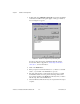
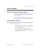
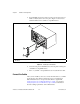
Table Of Contents
- Getting Started with Your PXI-8461 or PXI-8460 and the NI-CAN™ Software for Windows NT
- Support
- Important Information
- Compliance
- Contents
- About This Manual
- Chapter 1 Introduction
- Chapter 2 Installation and Configuration
- Chapter 3 Verify the Installation
- Chapter 4 Begin to Use the NI-CAN Software
- Appendix A Uninstalling the Hardware and Software
- Appendix B Cabling Requirements for PXI-8461 High-Speed CAN
- Appendix C Cabling Requirements for PXI-8460 Low-Speed CAN
- Appendix D Troubleshooting and Common Questions
- Appendix E Specifications
- Appendix F Technical Support Resources
- Glossary
- Figures
- Figure 2-1. Add/Remove Programs Properties Dialog Box
- Figure 2-2. Installing the PXI Hardware
- Figure 2-3. PXI-8461 That Is Working Properly
- Figure 2-4. NI-CAN Hardware Settings Dialog Box
- Figure 3-1. NI CAN Diagnostic Utility after Testing
- Figure A-1. Add/Remove Programs Properties Dialog Box
- Figure B-1. Pinout for 9-Pin D-Sub Connector
- Figure B-2. Pinout for 5-Pin Combicon-Style Pluggable Screw Terminal
- Figure B-3. PXI-8461 Part Locator Diagram
- Figure B-4. Power Source Jumpers
- Figure B-5. Termination Resistor Placement
- Figure B-6. Cabling Example
- Figure C-1. Pinout for 9-Pin D-Sub Connector
- Figure C-2. PXI-8460 Parts Locator Diagram
- Figure C-3. Power Source Jumpers
- Figure C-4. Termination Resistor Placement for Low-Speed CAN
- Figure C-5. Location of Termination Resistors on a PXI-8460
- Figure C-6. Preparing Lead Wires of Replacement Resistors
- Figure C-7. Cabling Example
- Tables
- Table B-1. Power Requirements for the CAN Physical Layer for Bus-Powered Versions
- Table B-2. ISO 11898 Specifications for Characteristics of a CAN_H and CAN_L Pair of Wires
- Table B-3. DeviceNet Cable Length Specifications
- Table C-1. Power Requirements for the Low-Speed CAN Physical Layer for Bus-Powered Versions
- Table C-2. ISO 11519-2 Specifications for Characteristics of a CAN_H and CAN_L Pair of Wires

Chapter 2 Installation and Configuration
© National Instruments Corporation 2-3 PXI-8461 or PXI-8460 and NI-CAN for Windows NT
Install the Hardware
This section describes how to install your PXI-8461or PXI-8460 hardware.
Check the Configuration of Your PXI-8461 or PXI-8460
If you plan to use your CAN board in a system where bus power is
available, you may want to configure the power supply jumpers on your
board. See Appendix B, Cabling Requirements for PXI-8461 High-Speed
CAN, for more information.
If you are installing a low-speed CAN board, you may need to change the
power supply jumpers or termination resistors. See Appendix C, Cabling
Requirements for PXI-8460 Low-Speed CAN, for more information.
Install Your PXI-8461 or PXI-8460
Caution
Before you remove the board from the package, touch the antistatic package to a
metal part of your system chassis to discharge electrostatic energy, which can damage
several components on your board.
1. Make sure that your PXI or CompactPCI chassis is turned off. Keep the
PXI or CompactPCI chassis plugged in so that it remains grounded
while you install the PXI board.
2. Choose an unused PXI or CompactPCI 5 V peripheral slot.
3. Remove the filler panel for the peripheral slot you have chosen.
4. Touch a metal part on your chassis to discharge any static electricity
that might be on your clothes or body.