
Computer Accessories User Manual
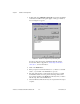
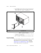
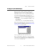
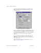
Table Of Contents
- Getting Started with Your PXI-8461 or PXI-8460 and the NI-CAN™ Software for Windows NT
- Support
- Important Information
- Compliance
- Contents
- About This Manual
- Chapter 1 Introduction
- Chapter 2 Installation and Configuration
- Chapter 3 Verify the Installation
- Chapter 4 Begin to Use the NI-CAN Software
- Appendix A Uninstalling the Hardware and Software
- Appendix B Cabling Requirements for PXI-8461 High-Speed CAN
- Appendix C Cabling Requirements for PXI-8460 Low-Speed CAN
- Appendix D Troubleshooting and Common Questions
- Appendix E Specifications
- Appendix F Technical Support Resources
- Glossary
- Figures
- Figure 2-1. Add/Remove Programs Properties Dialog Box
- Figure 2-2. Installing the PXI Hardware
- Figure 2-3. PXI-8461 That Is Working Properly
- Figure 2-4. NI-CAN Hardware Settings Dialog Box
- Figure 3-1. NI CAN Diagnostic Utility after Testing
- Figure A-1. Add/Remove Programs Properties Dialog Box
- Figure B-1. Pinout for 9-Pin D-Sub Connector
- Figure B-2. Pinout for 5-Pin Combicon-Style Pluggable Screw Terminal
- Figure B-3. PXI-8461 Part Locator Diagram
- Figure B-4. Power Source Jumpers
- Figure B-5. Termination Resistor Placement
- Figure B-6. Cabling Example
- Figure C-1. Pinout for 9-Pin D-Sub Connector
- Figure C-2. PXI-8460 Parts Locator Diagram
- Figure C-3. Power Source Jumpers
- Figure C-4. Termination Resistor Placement for Low-Speed CAN
- Figure C-5. Location of Termination Resistors on a PXI-8460
- Figure C-6. Preparing Lead Wires of Replacement Resistors
- Figure C-7. Cabling Example
- Tables
- Table B-1. Power Requirements for the CAN Physical Layer for Bus-Powered Versions
- Table B-2. ISO 11898 Specifications for Characteristics of a CAN_H and CAN_L Pair of Wires
- Table B-3. DeviceNet Cable Length Specifications
- Table C-1. Power Requirements for the Low-Speed CAN Physical Layer for Bus-Powered Versions
- Table C-2. ISO 11519-2 Specifications for Characteristics of a CAN_H and CAN_L Pair of Wires

Chapter 1 Introduction
PXI-8461 or PXI-8460 and NI-CAN for Windows NT 1-2 www.natinst.com
specification for CAN and is also optically isolated to 500 V. CAN
interfacing is accomplished using the Intel 82527 CAN controller chip.
The PXI-8461 supports a wide variety of transfer rates up to 1 Mb/s.
The PXI-8460 supports rates up to 125 kb/s. The CAN physical layer on the
PXI-8461 and PXI-8460 can be powered either internally (from the board)
or externally (from the bus cable power). The power source for the CAN
physical layer for each port is configured with a jumper.
PXI-8461 boards are available with two physical connector types:
• DB-9 D-Sub
• Combicon-style pluggable screw terminals
PXI-8460 boards are available with DB-9 D-Sub connectors.
The PXI-8461 and PXI-8460 use the Intel 386EX embedded processor
to implement time-critical features provided by the NI-CAN software.
The PXI-8461 and PXI-8460 communicate with the NI-CAN driver
through on-board shared memory and an interrupt.
NI-CAN Software Overview
The NI-CAN software includes a native, 32-bit multitasking Windows NT
kernel driver. The NI-CAN software is fully integrated into the
Windows NT operating system. You can configure it through the
Windows NT Control Panel and uninstall it through the Add/Remove
Programs applet of the Control Panel.
The NI-CAN software for Windows NT supports the concurrent use of
multiple CAN boards. For example, you can use both a PXI-8461 and
PCMCIA-CAN in the same system at the same time.
The NI-CAN software, along with the PXI hardware, transforms your
computer into a CAN interface with complete communications and bus
management capability. The NI-CAN software includes the following
components:
• Firmware (runs on embedded Intel 386EX)
• Device driver
• Diagnostic test utility
• Configuration utility