OPERATING INSTRUCTIONS NI 9852 2-Port, Low-Speed/Fault-Tolerant CAN Module
These operating instructions describe how to use the National Instruments (NI) 9852 module. For information about installing, configuring, and programming your system, refer to your system documentation. The NI 9852 module requires the NI 985x software (version 1.2 or higher) to be installed. The latest version of the NI 985x software is located at ni.com/downloads. The safety guidelines and specifications in this document are specific to the NI 9852.
Safety Guidelines for Hazardous Locations The NI 9852 is suitable for use in Class I, Division 2, Groups A, B, C, D, and T4 hazardous locations; Class 1, Zone 2, AEx nA II T4 and Ex nA II T4 hazardous locations; and nonhazardous locations only. Follow these guidelines if you are installing the NI 9852 in a potentially explosive environment. Not following these guidelines may result in serious injury or death.
For Zone 2 applications, install a protection device between the CAN signals and the NI 9852 CAN pins. The device must prevent the CAN Port-to-COM voltage from exceeding 55 V if there is a transient overvoltage condition. Caution Special Conditions for Hazardous Locations Use in Europe This equipment has been evaluated as EEx nA II T4 equipment under DEMKO Certificate No. 03 ATEX 0324020X. Each module is marked II 3G and is suitable for use in Zone 2 hazardous locations.
Each port has two isolated common pins (COM) that are internally connected to the isolated reference of the module and serve as the reference ground for CAN_H and CAN_L. Connect the CAN bus reference ground (sometimes referred to as CAN_V–) to the COM pin. Each port also has an optional shield pin, SHLD, that can be connected to a shielded CAN cable. Connecting SHLD may improve signal integrity and EMC performance in a noisy environment.
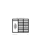
Table 1. Pin Assignments for CAN0 Connector 6 7 8 9 1 2 3 4 5 NI 9852 Operating Instructions Pin Signal 1 No Connection (NC) 2 CAN_L 3 COM0 4 NC 5 SHLD 6 COM0 7 CAN_H 8 NC 9 VSUP0 6 ni.
Table 2. Pin Assignments for CAN1 Connector 6 7 8 9 1 2 3 4 5 © National Instruments Corp.
CAN Bus Topology and Termination A CAN bus consists of two or more CAN nodes cabled together. The CAN_H and CAN_L pins of each node are connected to the main CAN bus cable through a short connection known as a “stub.” The pair of signal wires, CAN_H and CAN_L constitutes a transmission line. Every device on a low-speed/fault-tolerant CAN network requires a termination resistor for each CAN data line: RRTH for CAN_H and RRTL for CAN_L.
Low-speed/Fault-Tolerant CAN Device RTL CAN_L RTH CAN_H Low-speed/Fault-Tolerant CAN Device RTL CAN_L Low-speed/Fault-Tolerant CAN Device RTH CAN_H RTL CAN_L RTH CAN_H CAN_H CAN_L Figure 1. CAN Bus Topology and Termination Resistor Locations Connecting a CAN Bus to the NI 9852 Each port of the NI 9852 can be connected to any location on a CAN bus. Figure 2 shows one example of the connection of CAN0 of the NI 9852 directly to one CAN node, and CAN1 directly to another CAN node.
CAN Device (SHLD) (SHLD) CAN_H CAN_H CAN_L Vsup0 COM0 CAN Device (SHLD) CAN_H CAN_L Vsup1 COM1 CAN Cable (With Optional Shield) CAN_L CAN0 Vsup0 + – External Power Supply COM0 NI 9852 (SHLD) CAN_H CAN Cable (With Optional Shield) CAN_L Vsup1 + – CAN1 COM1 External Power Supply Figure 2. Connecting Both Ports of the NI 9852 to CAN Buses NI 9852 Operating Instructions 10 ni.
Cabling Requirements for NI 9852 This section deals with cabling specifications, termination resistors, cable lengths, and the number of CAN nodes that can exist in a system. Cable Specifications Cables should meet the physical medium requirements specified in ISO 11898, shown in Table 3. Belden cable (3084A) meets all of those requirements, and should be suitable for most applications. Table 3.
Determining the Necessary Termination Resistance for the Board Unlike High-Speed CAN, Low-Speed/Fault-Tolerant CAN requires termination at the Low-Speed/Fault-Tolerant CAN transceiver instead of on the cable itself. Termination requires two resistors, RTH for CAN_H and RTL for CAN_L. This configuration allows the Philips Fault-Tolerant CAN transceiver to detect and recover from bus faults.
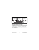
Number of CAN Nodes The maximum number of nodes depends on the electrical characteristics of the nodes on the network. If all of the nodes meet the requirements of Low-Speed/Fault-Tolerant CAN, up to 32 nodes may be connected to the bus. NI 9852 Hardware Overview The NI 9852 has two full-featured, independent CAN ports that are isolated from each other, and from the other modules in the system. Each port of the NI 9852 has a Philips SJA1000 CAN controller that is CAN 2.
VSUP0 Ext Pwr + Supply 0 _ COM0 CAN_H +5 V Reg CAN Transceiver CAN_L VSUP1 Rx Tx Rx Tx CAN Controller Rx Tx Rx Tx CAN Controller CAN0 Ext Pwr + Supply 1 _ COM1 CAN_H +5 V Reg CAN Transceiver CAN_L CAN1 Figure 3. NI 9852 Hardware Overview NI 9852 Operating Instructions 14 ni.
Sleep Mode (CompactRIO Only) You can enable sleep mode for the CompactRIO system in software. In sleep mode, the system consumes less power and may dissipate less heat. Typically, when a system is in sleep mode, you cannot communicate with the modules. Refer to the Specifications section for more information about power consumption and thermal dissipation. This system sleep mode should not be confused with the NI 9852 Transceiver Mode Sleep property, which sets only the CAN port to sleep mode.
Specifications The following specifications are typical for the range –40 to 70 °C unless otherwise noted. Low-Speed/Fault-Tolerant CAN Characteristics Transceiver........................................ Philips TJA1054A Max baud rate ................................... 125 Kbps CAN_H, CAN_L bus lines voltage............................................... –27 to +40 VDC Supply voltage range (VSUP0 /VSUP1 ) CAN0 ......................................... +8 to +36 VDC CAN1 ...................................
Note Contact NI for Bellcore MTBF specifications at other temperatures or for MIL-HDBK-217F specifications. Power Requirements Power consumption from chassis Active mode Transmitting ......................... 400 mW max Receiving ............................. 400 mW max Sleep mode ................................. 25 μW max Thermal dissipation (at 70 °C) Active mode ............................... 1.5 W max Sleep mode ................................. 1.
Safety Maximum Voltage1 Connect only voltages that are within these limits. Port-to-COM..................................... –27 to +40 VDC max, Measurement Category I Measurement Category I is for measurements performed on circuits not directly connected to the electrical distribution system referred to as MAINS voltage. MAINS is a hazardous live electrical supply system that powers equipment. This category is for measurements of voltages from specially protected secondary circuits.
Isolation Voltages Port-to-port Withstand.................................... 500 Vrms, 5 s Continuous ................................. 60 VDC, Measurement Category I Port-to-earth ground Withstand.................................... 500 Vrms, 5 s Continuous .................................
Hazardous Locations U.S. (UL) .......................................... Class I, Division 2, Groups A, B, C, D, T4; Class I, Zone 2, AEx nA II T4 Canada (C-UL) ................................. Class I, Division 2, Groups A, B, C, D, T4; Class I, Zone 2, Ex nA II T4 Europe (DEMKO)............................. EEx nA II T4 Environmental CompactRIO modules are intended for indoor use only. For outdoor use, mount the CompactRIO system in a suitably rated enclosure.
Storage humidity............................... 5 to 95% RH, noncondensing Maximum altitude............................. 2,000 m Pollution Degree (IEC 60664) .......... 2 Shock and Vibration To meet these specifications, you must panel mount the CompactRIO system. Operating vibration, random (IEC 60068-2-64) ................ 5 grms, 10 to 500 Hz Operating shock (IEC 60068-2-27)..............................
Electromagnetic Compatibility This product is designed to meet the requirements of the following standards of EMC for electical equipment for measurement, control, and laboratory use: • EN 61326 EMC requirements; Minimum Immunity • EN 55011 Emissions; Group 1, Class A • CE, C-Tick, ICES, and FCC Part 15 Emissions; Class A Note For EMC compliance, operate this device according to product documentation.
Note Refer to the Declaration of Conformity (DoC) for this product for any additional regulatory compliance information. To obtain the DoC for this product, visit ni.com/certification, search by model number or product line, and click the appropriate link in the Certification column. Environmental Management National Instruments is committed to designing and manufacturing products in an environmentally responsible manner.
Waste Electrical and Electronic Equipment (WEEE) EU Customers At the end of their life cycle, all products must be sent to a WEEE recycling center. For more information about WEEE recycling centers and National Instruments WEEE initiatives, visit ni.com/ environment/weee.htm. ⬉ᄤֵᙃѻક∵ᶧࠊㅵ⧚ࡲ⊩ ˄Ё RoHS˅ Ёᅶ᠋ National Instruments ヺড়Ё⬉ᄤֵᙃѻકЁ䰤ࠊՓ⫼ᶤѯ᳝ᆇ⠽䋼ᣛҸ (RoHS)DŽ ݇Ѣ National Instruments Ё RoHS ড়㾘ᗻֵᙃˈ䇋ⱏᔩ ni.com/environment/rohs_chinaDŽ (For information about China RoHS compliance, go to ni.
National Instruments Contact Information National Instruments corporate headquarters is located at 11500 North Mopac Expressway, Austin, Texas, 78759-3504. National Instruments also has offices located around the world to help address your support needs. For telephone support in the United States, create your service request at ni.com/support and follow the calling instructions or dial 512 795 8248.
South Africa 27 0 11 805 8197, Spain 34 91 640 0085, Sweden 46 (0) 8 587 895 00, Switzerland 41 56 2005151, Taiwan 886 02 2377 2222, Thailand 662 278 6777, Turkey 90 212 279 3031, United Kingdom 44 (0) 1635 523545 NI 9852 Operating Instructions 26 ni.
National Instruments, NI, ni.com, and LabVIEW are trademarks of National Instruments Corporation. Refer to the Terms of Use section on ni.com/legal for more information about National Instruments trademarks. Other product and company names mentioned herein are trademarks or trade names of their respective companies. For patents covering National Instruments products, refer to the appropriate location: Help»Patents in your software, the patents.txt file on your media, or ni.com/patents.