OPERATING INSTRUCTIONS AND SPECIFICATIONS NI 9481 4-Channel SPST Electromechanical Relay Module Français Deutsch ni.
This document describes how to use the National Instruments 9481 and includes specifications and terminal assignments for the NI 9481. Visit ni.com/info and enter rdsoftwareversion to determine which software you need for the modules you are using. For information about installing, configuring, and programming the system, refer to the system documentation. Visit ni.com/info and enter cseriesdoc for information about C Series documentation.
Safety Guidelines Operate the NI 9481 only as described in these operating instructions. This icon denotes that the component may be hot. Touching this component may result in bodily injury. Hot Surface Safety Guidelines for Hazardous Voltages If hazardous voltages are connected to the module, take the following precautions. A hazardous voltage is a voltage greater than 42.4 Vpk or 60 VDC to earth ground.
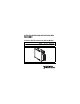
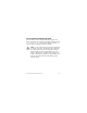
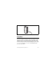
When module terminals are hazardous voltage LIVE (>42.4 Vpk/60 VDC), you must ensure that devices and circuits connected to the module are properly insulated from human contact. You must use the NI 9932 connector backshell kit to ensure that the terminals are not accessible. Caution Figure 1 shows the NI 9932 connector backshell. Figure 1. NI 9932 Connector Backshell NI 9481 Operating Instructions and Specifications 4 ni.
Safety Guidelines for Hazardous Locations The NI 9481 is suitable for use in Class I, Division 2, Groups A, B, C, D, T4 hazardous locations; Class I, Zone 2, AEx nC IIC T4 hazardous locations; and nonhazardous locations only. Follow these guidelines if you are installing the NI 9481 in a potentially explosive environment. Not following these guidelines may result in serious injury or death.
Special Conditions for Marine Applications Some modules are Lloyd’s Register (LR) Type Approved for marine applications. To verify Lloyd’s Register certification, visit ni.com/certification and search for the LR certificate, or look for the Lloyd’s Register mark on the module. To meet radio frequency emission requirements for marine applications, use shielded cables and install the system in a metal enclosure.
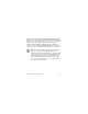
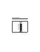
Connecting the NI 9481 The NI 9481 has a 10-terminal detachable screw-terminal connector that provides connections for 4 electromechanical relay channels. 0 CH0a CH0b CH1a CH1b CH2a CH2b CH3a CH3b NC NC 3 0 1 2 3 4 5 6 7 8 9 Figure 2. NI 9481 Terminal Assignments © National Instruments Corp.
Each electromechanical relay channel has two interchangeable terminals, CHa and CHb. Each channel has an LED that indicates the state of the channel. When a channel LED is lit, the channel is on. When the LED is dark, the channel is off. The LEDs are disabled when the chassis is in sleep mode. Refer to the Sleep Mode section for more information about sleep mode.
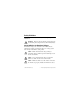
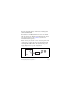
You must use 2-wire ferrules to create a secure connection when connecting more than one wire to a single terminal on the NI 9481. Note When the channel is turned on, the terminal connected to the load drives current or applies voltage to the load. When the channel is off, the terminal does not drive current or apply voltage to the load.
Figure 4. 10-Terminal Detachable Screw-Terminal Connector with Ferrule Sleep Mode This module supports a low-power sleep mode. Support for sleep mode at the system level depends on the chassis that the module is plugged into. Refer to the chassis manual for information about support for sleep mode. If the chassis supports sleep mode, refer to the software help for information about enabling sleep mode. Visit ni.com/info and enter cseriesdoc for information about C Series documentation.
Typically, when a system is in sleep mode, you cannot communicate with the modules. In sleep mode, the system consumes minimal power and may dissipate less heat than it does in normal mode. Refer to the Specifications section for more information about power consumption and thermal dissipation. Specifications The following specifications are typical for the range –40 to 70 °C unless otherwise noted. Output Characteristics Number of channels..........................
Switching capacity (resistive load) Switching voltage ....................... 60 VDC max, 250 Vrms max Switching current, per channel One channel on .................... 4 A max at 30 VDC, 1 A max at 60 VDC, 4 A max at 250 Vrms All channels on .................... 2 A max at 30 VDC, 1 A max at 60 VDC, 2 A max at 250 Vrms Resistance per channel, channel on......................................... 50 mΩ Switching rate ................................... 1 operation per second Relay release time...............
MTBF ............................................... 460,321 hours at 25 °C; Bellcore Issue 2, Method 1, Case 3, Limited Part Stress Method Note Contact NI for Bellcore MTBF specifications at other temperatures or for MIL-HDBK-217F specifications. Power Requirements Power consumption from chassis Active mode ............................... 580 mW max Sleep mode ................................. 5 mW max Thermal dissipation (at 70 °C) Active mode ............................... 1.5 W max Sleep mode ........
Physical Characteristics If you need to clean the module, wipe it with a dry towel. Screw-terminal wiring ...................... 12 to 24 AWG copper conductor wire with 10 mm (0.39 in.) of insulation stripped from the end Torque for screw terminals ............... 0.5 to 0.6 N · m (4.4 to 5.3 lb · in.) Ferrules ............................................. 0.25 mm2 to 2.5 mm2 Weight............................................... 150 g (5.
that provided by a standard wall outlet, for example, 115 V for U.S. or 230 V for Europe. Caution Do not connect the NI 9481 to signals or use for measurements within Measurement Categories III or IV. Isolation Channel-to-channel Continuous ........................... 250 Vrms Withstand ............................. 1,400 Vrms, verified by a 5 s dielectric withstand test Channel-to-earth ground Continuous ........................... 250 Vrms Withstand .............................
Safety Standards This product meets the requirements of the following standards of safety for electrical equipment for measurement, control, and laboratory use: • IEC 61010-1, EN 61010-1 • UL 61010-1, CSA 61010-1 Note For UL and other safety certifications, refer to the product label or the Online Product Certification section.
Note For the standards applied to assess the EMC of this product, refer to the Online Product Certification section. Note For EMC compliance, operate this device with shielded cabling.
Shock and Vibration To meet these specifications, you must panel mount the system and either affix ferrules to the ends of the terminal wires or use the NI 9932 backshell kit to protect the connections. Operating vibration, sinusoidal (IEC 60068-2-6) .............. 5 g, 40 to 500 Hz; 0.062 in. double amplitude, 10 to 40 Hz Environmental National Instruments C Series modules are intended for indoor use only but may be used outdoors if installed in a suitable enclosure.
Operating humidity (IEC 60068-2-56).............................. 10 to 90% RH, noncondensing Storage humidity (IEC 60068-2-56).............................. 5 to 95% RH, noncondensing Maximum altitude............................. 2,000 m Pollution Degree (IEC 60664) .......... 2 Environmental Management NI is committed to designing and manufacturing products in an environmentally responsible manner.
Waste Electrical and Electronic Equipment (WEEE) EU Customers At the end of the life cycle, all products must be sent to a WEEE recycling center. For more information about WEEE recycling centers and National Instruments WEEE initiatives, visit ni.com/ environment/weee. ⬉ᄤֵᙃѻક∵ᶧࠊㅵ⧚ࡲ⊩ ˄Ё RoHS˅ Ёᅶ᠋ National Instruments ヺড়Ё⬉ᄤֵᙃ ѻકЁ䰤ࠊՓ⫼ᶤѯ᳝ᆇ⠽䋼ᣛҸ (RoHS)DŽ݇Ѣ National Instruments Ё RoHS ড়㾘ᗻֵᙃˈ䇋ⱏᔩ ni.com/environment/rohs_chinaDŽ (For information about China RoHS compliance, go to ni.
Where to Go for Support The National Instruments Web site is your complete resource for technical support. At ni.com/support you have access to everything from troubleshooting and application development self-help resources to email and phone assistance from NI Application Engineers. National Instruments corporate headquarters is located at 11500 North Mopac Expressway, Austin, Texas, 78759-3504. National Instruments also has offices located around the world to help address your support needs.
Korea 82 02 3451 3400, Lebanon 961 (0) 1 33 28 28, Malaysia 1800 887710, Mexico 01 800 010 0793, Netherlands 31 (0) 348 433 466, New Zealand 0800 553 322, Norway 47 (0) 66 90 76 60, Poland 48 22 3390150, Portugal 351 210 311 210, Russia 7 495 783 6851, Singapore 1800 226 5886, Slovenia 386 3 425 42 00, South Africa 27 0 11 805 8197, Spain 34 91 640 0085, Sweden 46 (0) 8 587 895 00, Switzerland 41 56 2005151, Taiwan 886 02 2377 2222, Thailand 662 278 6777, Turkey 90 212 279 3031, United Kingdom 44 (0) 1635 5
National Instruments, NI, ni.com, and LabVIEW are trademarks of National Instruments Corporation. Refer to the Terms of Use section on ni.com/legal for more information about National Instruments trademarks. Other product and company names mentioned herein are trademarks or trade names of their respective companies. For patents covering National Instruments products/technology, refer to the appropriate location: Help»Patents in your software, the patents.