OPERATING INSTRUCTIONS AND SPECIFICATIONS NI 9478 16-Channel, 0–50 V, Sinking Digital Output Module with Programmable Current Limits Français Deutsch ni.
This document describes how to use the National Instruments 9478 and includes specifications and pin assignments for the NI 9478. Visit ni.com/info and enter rdsoftwareversion to determine which software you need for the modules you are using. For information about installing, configuring, and programming the system, refer to the system documentation. Visit ni.com/info and enter cseriesdoc for information about C Series documentation.
Safety Guidelines Operate the NI 9478 only as described in these operating instructions. This icon denotes that the component may be hot. Touching this component may result in bodily injury. Hot Surface Safety Guidelines for Hazardous Locations The NI 9478 is suitable for use in Class I, Division 2, Groups A, B, C, D, T4 hazardous locations; Class I, Zone 2, AEx nA IIC T4, and Ex nA IIC T4 hazardous locations; and nonhazardous locations only.
Substitution of components may impair suitability for Class I, Division 2. Caution For Zone 2 applications, install the system in an enclosure rated to at least IP 54 as defined by IEC 60529 and EN 60529. Caution For Zone 2 applications, install a protection device across the external power supply and the COM pin. The device must prevent the external power supply voltage from exceeding 70 V if there is a transient overvoltage condition.
Special Conditions for Marine Applications Some modules are Lloyd’s Register (LR) Type Approved for marine applications. To verify Lloyd’s Register certification, visit ni.com/certification and search for the LR certificate, or look for the Lloyd’s Register mark on the module. To meet radio frequency emission requirements for marine applications, use shielded cables and install the system in a metal enclosure.
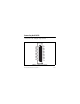
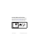
Connecting the NI 9478 The NI 9478 has a 37-pin DSUB connector that provides connections for the 16 digital output channels. COM COM COM COM COM COM COM COM Vsup Vsup COM COM COM COM COM COM COM COM 20 21 22 23 24 25 26 27 28 29 30 31 32 33 34 35 36 37 1 2 3 4 5 6 7 8 9 10 11 12 13 14 15 16 17 18 19 DO0 DO1 DO2 DO3 DO4 DO5 DO6 DO7 Vsup Vsup DO8 DO9 DO10 DO11 DO12 DO13 DO14 DO15 NC Figure 1. NI 9478 Pin Assignments NI 9478 Operating Instructions and Specifications 6 ni.
Each channel of the NI 9478 has a DO pin to which you can connect the load you want to control. Each channel also has a COM pin. National Instruments recommends you provide independent COM wiring for each channel to minimize current flow in the COM wiring. The COM pins are all connected together internally. You must connect an external power supply to the NI 9478. This power supply provides the current for the devices you connect to the module.
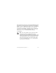
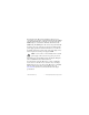
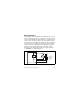
Connect the device to DO and the positive lead of the power supply. Refer to Figure 2 for an illustration of how to connect a device to the NI 9478. Vsup Cable Clamp DO COM Device + External Power – Supply NI 9478 Figure 2. Connecting a Device to the NI 9478 You must connect the Vsup pin to the power supply to enable a weak cable clamping diode that protects the module from cable inductance flyback. This flyback voltage results from small amounts of energy stored in the inductance of the cabling.
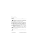
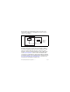
Protecting the Module from Flyback Voltages If the module is switching an inductive or energy-storing device such as a solenoid, motor, or relay, and the device does not have flyback protection, install an external flyback diode as shown in Figure 3. Refer to the Using Long Cables section for more information about protection from cable inductance flyback. Vsup Cable Clamp Device DO + External Power – Supply COM NI 9478 Figure 3. Connecting a Flyback Diode to the NI 9478 © National Instruments Corp.
Using Long Cables The inductance of the cabling that connects the NI 9478, the loads, and the external supply stores up energy when a channel is on and passing current through the cables. Each time a channel is turned off, the energy stored in the cables is released as flyback voltage and dissipates as heat in the NI 9478. The total power dissipated in the module increases with higher switching frequencies, higher currents, and longer cable lengths.
You can reduce the effective length of the cable by adding a capacitor close to the NI 9478 across the power supply leads and adding a diode from the digital output line to the Vsup pin line. National Instruments recommends that you use a capacitor with a capacitance of at least 20 μF. In this case, the effective length of the cable is the distance from the output pin, through the new diode, through the capacitor, and back to the COM pin, as shown in Figure 5.
I/O Protection The NI 9478 provides protection against overcurrent and short-circuit conditions. Output Current Limit Thresholds The NI 9478 provides two configurable current limit thresholds for the module, Limit A and Limit B. The NI 9478 continuously monitors the current through each output channel and detects if the current exceeds either of the current limit thresholds.
Some applications require a large inrush current when a channel is first turned on. If this inrush current exceeds the maximum current limit threshold, you may need to disable overcurrent protection by programming the channel to have no current limit. Refer to the software help for more information about configuring current limits. Visit ni.com/info and enter cseriesdoc for information about C Series documentation.
Overcurrent Refresh The NI 9478 provides an overcurrent refresh setting that enables a channel to automatically recover within the specified overcurrent refresh period if the channel exceeds its current limit threshold. If overcurrent refresh is disabled, the channel remains off after an overcurrent condition until software sends a command to turn the channel back on. Refer to the software help for more information about overcurrent refresh. Visit ni.
for that channel. Use the following equation to calculate the percentage of the total power budget each output channel uses in your application. 2 2 P = 4% ⎛⎝ I out ⎞⎠ + 0.12% ( length – 0.2 ) ⎛⎝ I out ⎞⎠ + 0.
Example One You are driving a load with 2.0 meters of cable through a cycle in which the NI 9478 is on and passing 1.25 A of current for 40 μs, then off for 10 μs. The output period is 50 μs (40 μs + 10 μs) so the output frequency is 20 kHz. The channel uses 14.8% of the total power budget, as shown in the following equation. 2 2 4% ( 1.25 ) + [ 0.12% ( 2.0 – 0.2 ) ( 1.25 ) + 0.04% ( 1.25 + 1 ) ]20 = 14.8% NI 9478 Operating Instructions and Specifications 16 ni.
Example Two You are driving a load with 2.0 meters of cable through a cycle in which the NI 9478 first is constantly on and passing 3 A of current for 0.25 seconds, then drives the load at 20 kHz with 1.25 A current for 1.25 seconds, then drives the load off for 4 seconds. While the NI 9478 is constantly on, the output frequency is 0 kHz and the channel uses 36% (4% × 32) of the total power budget. Example One shows that while the NI 9478 is driving at 20 kHz, the channel uses 14.
Sleep Mode This module supports a low-power sleep mode. Support for sleep mode at the system level depends on the chassis that the module is plugged into. Refer to the chassis manual for information about support for sleep mode. If the chassis supports sleep mode, refer to the software help for information about enabling sleep mode. Visit ni.com/info and enter cseriesdoc for information about C Series documentation. Typically, when a system is in sleep mode, you cannot communicate with the modules.
Specifications The following specifications are typical for the range –40 to 70 °C unless otherwise noted. All voltages are relative to COM unless otherwise noted. Output Characteristics Number of channels.......................... 16 digital output channels Output type ....................................... Sinking Power-on output state ....................... Channels off Output voltage (V0) ........................... I0 R0 External power supply voltage range (Vsup)...........................
Switched output current (10 kHz)1, per channel All channels on........................... 1 A max Four channels on ........................ 2 A max One channel on........................... 4 A max Switched output current (20 kHz)1, per channel All channels on........................... 0.75 A max Four channels on ........................ 1.67 A max One channel on........................... 3.33 A max Output impedance (R0) ..................... 50 mΩ max Reversed-voltage protection .............
Overcurrent protection threshold selection per channel......................... Limit A, Limit B, or No Limit Overcurrent shutoff response time.... 1 μs Overcurrent refresh configuration .... Enabled or Disabled Overcurrent refresh period................ 20–2550 μs in 10 μs increments Overcurrent refresh period accuracy ............................................ ±7% max Propagation delay ............................. 250 ns max MTBF ...............................................
Power Requirements Power consumption from chassis Active mode ............................... 1 W max Sleep mode ................................. 25 μW max Thermal dissipation (at 70 °C) Active mode ............................... 1.5 W max Sleep mode ................................. 25 μW max Physical Characteristics If you need to clean the module, wipe it with a dry towel. Weight............................................... 148 g (5.2 oz) NI 9478 Operating Instructions and Specifications 22 ni.
Safety Maximum Voltage1 Connect only voltages that are within the following limits. Vsup-to-COM..................................... 50 VDC, Measurement Category I Measurement Category I is for measurements performed on circuits not directly connected to the electrical distribution system referred to as MAINS voltage. MAINS is a hazardous live electrical supply system that powers equipment. This category is for measurements of voltages from specially protected secondary circuits.
Isolation Voltages Channel-to-channel........................... No isolation between channels Channel-to-earth ground Continuous ................................. 60 VDC, Measurement Category I Withstand....................................
Hazardous Locations U.S. (UL) .......................................... Class I, Division 2, Groups A, B, C, D, T4; Class I, Zone 2, AEx nA IIC T4 Canada (C-UL) ................................. Class I, Division 2, Groups A, B, C, D, T4; Class I, Zone 2, Ex nA IIC T4 Europe (DEMKO)............................. Ex nA IIC T4 Environmental National Instruments C Series modules are intended for indoor use only but may be used outdoors if installed in a suitable enclosure.
Operating humidity (IEC 60068-2-56).............................. 10 to 90% RH, noncondensing Storage humidity (IEC 60068-2-56).............................. 5 to 95% RH, noncondensing Maximum altitude............................. 2,000 m Pollution Degree (IEC 60664) .......... 2 Shock and Vibration To meet these specifications, you must panel mount the system. Operating vibration Random (IEC 60068-2-64)......... 5 grms, 10 to 500 Hz Sinusoidal (IEC 60068-2-6) .......
Electromagnetic Compatibility This product is designed to meet the requirements of the following standards of EMC for electrical equipment for measurement, control, and laboratory use: • EN 61326 EMC requirements; Industrial Immunity • EN 55011 Emissions; Group 1, Class A • CE, C-Tick, ICES, and FCC Part 15 Emissions; Class A Note For EMC compliance, operate this device with shielded cabling.
ni.com/certification, search by module number or product line, and click the appropriate link in the Certification column. Environmental Management National Instruments is committed to designing and manufacturing products in an environmentally responsible manner. NI recognizes that eliminating certain hazardous substances from our products is beneficial not only to the environment but also to NI customers. For additional environmental information, refer to the NI and the Environment Web page at ni.
⬉ᄤֵᙃѻક∵ᶧࠊㅵ⧚ࡲ⊩ ˄Ё RoHS˅ Ёᅶ᠋ National Instruments ヺড়Ё⬉ᄤֵᙃ ѻકЁ䰤ࠊՓ⫼ᶤѯ᳝ᆇ⠽䋼ᣛҸ (RoHS)DŽ݇Ѣ National Instruments Ё RoHS ড়㾘ᗻֵᙃˈ䇋ⱏᔩ ni.com/environment/rohs_chinaDŽ (For information about China RoHS compliance, go to ni.com/ environment/rohs_china.) © National Instruments Corp.
Where to Go for Support The National Instruments Web site is your complete resource for technical support. At ni.com/support you have access to everything from troubleshooting and application development self-help resources to email and phone assistance from NI Application Engineers. National Instruments corporate headquarters is located at 11500 North Mopac Expressway, Austin, Texas, 78759-3504. National Instruments also has offices located around the world to help address your support needs.
Korea 82 02 3451 3400, Lebanon 961 (0) 1 33 28 28, Malaysia 1800 887710, Mexico 01 800 010 0793, Netherlands 31 (0) 348 433 466, New Zealand 0800 553 322, Norway 47 (0) 66 90 76 60, Poland 48 22 3390150, Portugal 351 210 311 210, Russia 7 495 783 6851, Singapore 1800 226 5886, Slovenia 386 3 425 42 00, South Africa 27 0 11 805 8197, Spain 34 91 640 0085, Sweden 46 (0) 8 587 895 00, Switzerland 41 56 2005151, Taiwan 886 02 2377 2222, Thailand 662 278 6777, Turkey 90 212 279 3031, United Kingdom 44 (0) 1635 5
National Instruments, NI, ni.com, and LabVIEW are trademarks of National Instruments Corporation. Refer to the Terms of Use section on ni.com/legal for more information about National Instruments trademarks. Other product and company names mentioned herein are trademarks or trade names of their respective companies. For patents covering National Instruments products, refer to the appropriate location: Help»Patents in your software, the patents.txt file on your CD, or ni.com/patents.