OPERATING INSTRUCTIONS AND SPECIFICATIONS NI 9472/9474 8-Channel Digital Output Modules Français Deutsch ni.
This document describes how to use the National Instruments 9472 and National Instruments 9474 and includes specifications and terminal or pin assignments. In this document, the NI 9472/9474 with screw terminal and NI 9472 with DSUB are referred to inclusively as the NI 9472/9474. Visit ni.com/info and enter rdsoftwareversion to determine which software you need for the modules you are using. For information about installing, configuring, and programming the system, refer to the system documentation.
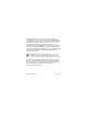
This icon denotes that the component may be hot. Touching this component may result in bodily injury. Hot Surface Safety Guidelines for Hazardous Voltages You can connect hazardous voltages only to the NI 9472/9474 with screw terminal. Do not connect hazardous voltages to the NI 9472 with DSUB. If hazardous voltages are connected to the module, take the following precautions. A hazardous voltage is a voltage greater than 42.4 Vpk or 60 VDC to earth ground.
and circuits connected to the module are properly insulated from human contact. You must use the NI 9932 connector backshell kit to ensure that the terminals are not accessible. Figure 1 shows the NI 9932 connector backshell. Note You can use the NI 9932 connector backshell only with the NI 9472/9474 with screw terminal. Figure 1. NI 9932 Connector Backshell NI 9472/9474 4 ni.
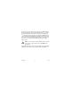
Safety Guidelines for Hazardous Locations The NI 9472/9474 is suitable for use in Class I, Division 2, Groups A, B, C, D, T4 hazardous locations; Class I, Zone 2, AEx nC IIC T4 and Ex nC IIC T4 hazardous locations; and nonhazardous locations only. Follow these guidelines if you are installing the NI 9472/9474 in a potentially explosive environment. Not following these guidelines may result in serious injury or death.
For Zone 2 applications, install a protection device between the Vsup and COM terminals on the NI 9472/9474. The device must prevent the input Vsup-to-COM voltage from exceeding 42 V if there is a transient overvoltage condition. Caution Special Conditions for Hazardous Locations Use in Europe This equipment has been evaluated as EEx nC IIC T4 equipment under DEMKO Certificate No. 03 ATEX 0324020X. Each module is marked II 3G and is suitable for use in Zone 2 hazardous locations.
Special Conditions for Marine Applications Some modules are Lloyd’s Register (LR) Type Approved for marine applications. To verify Lloyd’s Register certification, visit ni.com/certification and search for the LR certificate, or look for the Lloyd’s Register mark on the module. To meet radio frequency emission requirements for marine applications, use shielded cables and install the system in a metal enclosure.
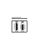
Connecting the NI 9472/9474 The NI 9472/9474 provides connections for eight digital output channels. DO0 DO1 DO2 DO3 DO4 DO5 DO6 DO7 Vsup COM 0 3 0 3 4 7 4 7 0 1 2 3 4 5 6 7 8 9 DO0 Vsup DO1 DO2 Vsup DO3 DO4 Vsup DO5 DO6 Vsup DO7 14 1 15 2 16 3 17 4 18 5 19 6 20 7 21 8 9 22 10 23 11 24 12 25 13 COM Vsup COM COM Vsup COM COM Vsup COM COM Vsup COM COM Figure 2. NI 9472/9474 Terminal and Pin Assignments NI 9472/9474 8 ni.
The NI 9472/9474 with screw terminal has a 10-terminal, detachable screw-terminal connector. The NI 9472 with DSUB has a 25-pin DSUB connector. Each channel of the NI 9472/9474 has a terminal or pin, DO, to which you can connect a device. The eight digital output channels are internally referenced to the common terminal or pin, COM. National Instruments recommends you provide independent COM and Vsup wiring for each channel of the NI 9472 with DSUB to minimize current flow in the COM and Vsup wiring.
You must connect an external power supply to the NI 9472/9474. This power supply provides the current for the devices you connect to the module. Connect the positive lead of the power supply to Vsup and the negative lead of the power supply to COM. The Vsup pins on the NI 9472 with DSUB are internally connected. You can connect only one external voltage supply to the device. Refer to the Specifications section for information about the power supply voltage range.
You can directly connect the NI 9472/9474 to a variety of industrial devices such as solenoids, motors, actuators, relays, and lamps. Make sure the devices you connect to the NI 9472/9474 are compatible with the output specifications of the module. Refer to the Specifications section for more information about the output specifications. Connect the device to DO and connect the common of the device to COM. Refer to Figure 3 for an illustration of how to connect a device to the NI 9472/9474.
Increasing Current Drive Each channel of the NI 9472 has a continuous output current of 0.75 A, and each channel of the NI 9474 has a continuous output current of 1 A. If you want to increase the output current to a device, you can connect any number of channels together in parallel. For example, using the NI 9474, if you want to drive 4 A of current, connect DO<0...3> in parallel as shown in Figure 4.
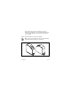
Wiring for High-Vibration Applications If an application using the NI 9472/9474 with screw terminal is subject to high vibration, National Instruments recommends that you either use ferrules to terminate wires to the detachable screw-terminal connector or use the NI 9932 backshell kit to protect the connections. Refer to Figure 5 for an illustration of using ferrules. Refer to Figure 1 for an illustration of the NI 9932 connector backshell. Figure 5.
I/O Protection The NI 9472/9474 is short-circuit proof in accordance with IEC 1131-2 and provides overcurrent protection. Understanding Short-Circuit-Proof Devices Each channel on the NI 9472/9474 has circuitry that protects it from current surges resulting from short circuits.
more information about the maximum continuous output current, short-circuit behavior, and short-circuit trip time. You also can refer to the IEC 1131-2 standard for more information about short-circuit-proof devices. Tip Because the NI 9472/9474 module includes internal flyback diodes, you do not need to add external diodes when connecting to switching energy storing devices.
the channel is in an overcurrent state, measure the voltage between DO and Vsup. If the voltage is equal to the voltage of the external power supply connected to the module, the channel is in an overcurrent state. Resetting Channels After an Overcurrent Condition After you have determined and fixed the cause of the overcurrent condition, reset the channel by turning it off. Alternatively, you can disconnect the external power supply from the module.
Typically, when a system is in sleep mode, you cannot communicate with the modules. In sleep mode, the system consumes minimal power and may dissipate less heat than it does in normal mode. Refer to the Specifications section for more information about power consumption and thermal dissipation. Specifications The following specifications are typical for the range –40 to 70 °C unless otherwise noted. All voltages are relative to COM unless otherwise noted.
Output impedance (R0) Typical ........................................ 0.07 Ω Maximum ................................... 0.13 Ω Continuous output current (I0), per channel NI 9472....................................... 0.75 A max NI 9474....................................... 1 A max Output voltage (V0) ........................... Vsup – (I0 · R0) I/O protection Voltage........................................ 30 VDC max Reversed voltage ........................
Output delay time (full load) NI 9472....................................... 100 μs max NI 9474....................................... 1 μs max MTBF NI 9472....................................... 1,113,301 hours at 25 °C; Bellcore Issue 2, Method 1, Case 3, Limited Part Stress Method NI 9474.......................................
Thermal dissipation (at 70 °C) Active mode ............................... 1.5 W max Sleep mode ................................. 55 mW max NI 9474 Power Requirements Power consumption from chassis Active mode ............................... 660 mW max Sleep mode ................................. 0.6 mW max Thermal dissipation (at 70 °C) Active mode ............................... 1.5 W max Sleep mode ................................. 0.
Ferrules ............................................. 0.25 mm2 to 2.5 mm2 Weight NI 9472/9474 with screw terminal ............................ 150 g (5.3 oz) NI 9472 with DSUB................... 145 g (5.1 oz) Safety NI 9472/9474 with Screw Terminal Safety Voltages Connect only voltages that are within the following limits. Channel-to-COM .............................. 30 VDC max Isolation Channel-to-channel .................... None Channel-to-earth ground Continuous ...........................
This category refers to local-level electrical distribution, such as that provided by a standard wall outlet, for example, 115 V for U.S. or 230 V for Europe. Caution Do not connect the NI 9472/9474 with screw terminal to signals or use for measurements within Measurement Categories III or IV. NI 9472 with DSUB Safety Voltages Connect only voltages that are within the following limits. Channel-to-COM .............................. 30 VDC max Isolation Channel-to-channel ....................
supply system that powers equipment. This category is for measurements of voltages from specially protected secondary circuits. Such voltage measurements include signal levels, special equipment, limited-energy parts of equipment, circuits powered by regulated low-voltage sources, and electronics. Caution Do not connect the NI 9472 with DSUB to signals or use for measurements within Measurement Categories II, III, or IV.
Hazardous Locations U.S. (UL) .......................................... Class I, Division 2, Groups A, B, C, D, T4; Class I, Zone 2, AEx nC IIC T4 Canada (C-UL) ................................. Class I, Division 2, Groups A, B, C, D, T4; Class I, Zone 2, Ex nC IIC T4 Europe (DEMKO)............................. EEx nC IIC T4 NI 9472/9474 24 ni.
Environmental National Instruments C Series modules are intended for indoor use only but may be used outdoors if installed in a suitable enclosure. Refer to the manual for the chassis you are using for more information about meeting these specifications. Operating temperature (IEC 60068-2-1, IEC 60068-2-2) ..... –40 to 70 °C Storage temperature (IEC 60068-2-1, IEC 60068-2-2) ..... –40 to 85 °C Ingress protection.............................. IP 40 Operating humidity (IEC 60068-2-56).........................
Shock and Vibration To meet these specifications, you must panel mount the system. If you are using the NI 9472/9474 with screw terminal, you also must either affix ferrules to the ends of the terminal wires or use the NI 9932 backshell kit to protect the connections. Operating vibration Random (IEC 60068-2-64)......... 5 grms, 10 to 500 Hz Sinusoidal (IEC 60068-2-6) ....... 5 g, 10 to 500 Hz Operating shock (IEC 60068-2-27)..............................
Note For EMC compliance, operate this device with shielded cabling. CE Compliance This product meets the essential requirements of applicable European directives, as amended for CE markings, as follows: • 2006/95/EC; Low-Voltage Directive (safety) • 2004/108/EC; Electromagnetic Compatibility Directive (EMC) Note Refer to the Declaration of Conformity (DoC) for this product for any additional regulatory compliance information. To obtain the DoC for this product, visit ni.
Environmental Management National Instruments is committed to designing and manufacturing products in an environmentally responsible manner. NI recognizes that eliminating certain hazardous substances from our products is beneficial not only to the environment but also to NI customers. For additional environmental information, refer to the NI and the Environment Web page at ni.com/environment.
⬉ᄤֵᙃѻક∵ᶧࠊㅵ⧚ࡲ⊩ ˄Ё RoHS˅ Ёᅶ᠋ National Instruments ヺড়Ё⬉ᄤֵᙃ ѻકЁ䰤ࠊՓ⫼ᶤѯ᳝ᆇ⠽䋼ᣛҸ (RoHS)DŽ݇Ѣ National Instruments Ё RoHS ড়㾘ᗻֵᙃˈ䇋ⱏᔩ ni.com/environment/rohs_chinaDŽ (For information about China RoHS compliance, go to ni.com/ environment/rohs_china.) Where to Go for Support The National Instruments Web site is your complete resource for technical support. At ni.
telephone support outside the United States, contact your local branch office: Australia 1800 300 800, Austria 43 662 457990-0, Belgium 32 (0) 2 757 0020, Brazil 55 11 3262 3599, Canada 800 433 3488, China 86 21 5050 9800, Czech Republic 420 224 235 774, Denmark 45 45 76 26 00, Finland 358 (0) 9 725 72511, France 01 57 66 24 24, Germany 49 89 7413130, India 91 80 41190000, Israel 972 3 6393737, Italy 39 02 41309277, Japan 0120-527196, Korea 82 02 3451 3400, Lebanon 961 (0) 1 33 28 28, Malaysia 1800 887710,
National Instruments, NI, ni.com, and LabVIEW are trademarks of National Instruments Corporation. Refer to the Terms of Use section on ni.com/legal for more information about National Instruments trademarks. Other product and company names mentioned herein are trademarks or trade names of their respective companies. For patents covering National Instruments products, refer to the appropriate location: Help»Patents in your software, the patents.txt file on your media, or ni.com/patents.