OPERATING INSTRUCTIONS AND SPECIFICATIONS NI 9426 32-Channel, 24 V, Sourcing Digital Input Module Français Deutsch ni.
This document describes how to use the National Instruments 9426 and includes specifications and pin assignments for the NI 9426. Visit ni.com/info and enter rdsoftwareversion to determine which software you need for the modules you are using. For information about installing, configuring, and programming the system, refer to the system documentation. Visit ni.com/info and enter cseriesdoc for information about C Series documentation.
Safety Guidelines for Hazardous Voltages If hazardous voltages are connected to the module, take the following precautions. A hazardous voltage is a voltage greater than 42.4 Vpk or 60 VDC to earth ground. Ensure that hazardous voltage wiring is performed only by qualified personnel adhering to local electrical standards. Caution Caution Do not mix hazardous voltage circuits and human-accessible circuits on the same module.
Ex nA IIC T4 hazardous locations; and nonhazardous locations only. Follow these guidelines if you are installing the NI 9426 in a potentially explosive environment. Not following these guidelines may result in serious injury or death. Caution Do not disconnect I/O-side wires or connectors unless power has been switched off or the area is known to be nonhazardous. Do not remove modules unless power has been switched off or the area is known to be nonhazardous.
Special Conditions for Hazardous Locations Use in Europe This equipment has been evaluated as Ex nA IIC T4 equipment under DEMKO Certificate No. 07 ATEX 0626664X. Each module is marked II 3G and is suitable for use in Zone 2 hazardous locations. If you are using the NI 9426 in Gas Group IIC hazardous locations or in ambient temperatures of –40 °C ≤ Ta ≤ 70 °C, you must use the device in an NI chassis that has been evaluated as EEx nC IIC T4, Ex nA IIC T4, or Ex nL IIC T4 equipment.
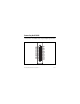
Connecting the NI 9426 The NI 9426 has a 37-pin DSUB connector that provides connections for 32 simultaneously-sampled digital input channels. DI16 DI17 DI18 DI19 DI20 DI21 DI22 DI23 Vsup Vsup DI24 DI25 DI26 DI27 DI28 DI29 DI30 DI31 20 21 22 23 24 25 26 27 28 29 30 31 32 33 34 35 36 37 1 2 3 4 5 6 7 8 9 10 11 12 13 14 15 16 17 18 19 DI0 DI1 DI2 DI3 DI4 DI5 DI6 DI7 Vsup Vsup DI8 DI9 DI10 DI11 DI12 DI13 DI14 DI15 NC Figure 1.
Each channel has a DI pin to which you can connect a digital input signal. The NI 9426 has four supply pins, Vsup, that are internally connected to the isolated reference of the module. The NI 9426 has sourcing inputs, meaning the DI pin sources current from Vsup to the sinking output device. The NI 9426 internally limits current signals connected to DI. For more information about input current levels, refer to the Specifications section.
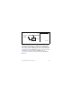
Vsup External + Power Supply _ DI Sinking-Output Device NI 9426 Figure 2. Connecting a Device to the NI 9426 (Three-Wire Device Shown) The NI 9426 channel registers as ON when the sinking-output device drives the input below Vsup and meets the input ON range. The channel registers as OFF when the device does not drive the input low and is in the input OFF range. If no device is connected to the DI pin, the channel registers as OFF.
Sleep Mode This module supports a low-power sleep mode. Support for sleep mode at the system level depends on the chassis that the module is plugged into. Refer to the chassis manual for information about support for sleep mode. If the chassis supports sleep mode, refer to the software help for information about enabling sleep mode. Visit ni.com/info and enter cseriesdoc for information about C Series documentation. Typically, when a system is in sleep mode, you cannot communicate with the modules.
Input type .......................................... Sourcing Digital logic levels OFF state Input voltage1 ....................... ≥ (Vsup – 5 V) Input current......................... ≤150 μA from DI pin ON state Input voltage1 ....................... ≤ (Vsup – 10 V) Input current......................... ≥330 μA from DI pin Hysteresis Input voltage ........................ 1.9 V min Input current......................... 65 μA min Input impedance................................
Hold time1 ......................................... 0 s min Setup time2 ........................................ 1 μs min Update/transfer time3 ........................ 7 μs max MTBF ............................................... 955,723 hours at 25 °C; Bellcore Issue 2, Method 1, Case 3, Limited Part Stress Method Note Contact NI for Bellcore MTBF specifications at other temperatures or for MIL-HDBK-217F specifications.
Power Requirements Power consumption from chassis Active mode ............................... 615 mW max Sleep mode1 ................................ 5 mW max Thermal dissipation (at 70 °C) Active mode ............................... 1.35 W max Sleep mode ................................. 1.16 W max Physical Characteristics If you need to clean the module, wipe it with a dry towel. Weight............................................... 147 g (5.
Isolation Channel-to-channel .................... None Channel-to-earth ground Continuous ........................... 60 VDC, Measurement Category I Withstand ............................. 1,000 Vrms, verified by a 5 s dielectric withstand test Measurement Category I is for measurements performed on circuits not directly connected to the electrical distribution system referred to as MAINS voltage. MAINS is a hazardous live electrical supply system that powers equipment.
Safety Standards This product is designed to meet the requirements of the following standards of safety for electrical equipment for measurement, control, and laboratory use: • IEC 61010-1, EN 61010-1 • UL 61010-1, CSA 61010-1 Note For UL and other safety certifications, refer to the product label or visit ni.com/certification, search by module number or product line, and click the appropriate link in the Certification column. Hazardous Locations U.S. (UL) ..........................................
Environmental National Instruments C Series modules are intended for indoor use only but may be used outdoors if installed in a suitable enclosure. Refer to the manual for the chassis you are using for more information about meeting these specifications. Operating temperature (IEC 60068-2-1, IEC 60068-2-2) ..... –40 to 70 °C Storage temperature (IEC 60068-2-1, IEC 60068-2-2) ..... –40 to 85 °C Ingress protection.............................. IP 40 Operating humidity (IEC 60068-2-56).........................
Shock and Vibration To meet these specifications, you must panel mount the system. Operating vibration Random (IEC 60068-2-64)......... 5 grms, 10 to 500 Hz Sinusoidal (IEC 60068-2-6) ....... 5 g, 10 to 500 Hz Operating shock (IEC 60068-2-27)..............................
CE Compliance This product meets the essential requirements of applicable European directives, as amended for CE markings, as follows: • 2006/95/EC; Low-Voltage Directive (safety) • 2004/108/EC; Electromagnetic Compatibility Directive (EMC) Note Refer to the Declaration of Conformity (DoC) for this product for any additional regulatory compliance information. To obtain the DoC for this product, visit ni.
For additional environmental information, refer to the NI and the Environment Web page at ni.com/environment. This page contains the environmental regulations and directives with which NI complies, as well as other environmental information not included in this document. Waste Electrical and Electronic Equipment (WEEE) EU Customers At the end of their life cycle, all products must be sent to a WEEE recycling center.
Where to Go for Support The National Instruments Web site is your complete resource for technical support. At ni.com/support you have access to everything from troubleshooting and application development self-help resources to email and phone assistance from NI Application Engineers. National Instruments corporate headquarters is located at 11500 North Mopac Expressway, Austin, Texas, 78759-3504. National Instruments also has offices located around the world to help address your support needs.
Korea 82 02 3451 3400, Lebanon 961 (0) 1 33 28 28, Malaysia 1800 887710, Mexico 01 800 010 0793, Netherlands 31 (0) 348 433 466, New Zealand 0800 553 322, Norway 47 (0) 66 90 76 60, Poland 48 22 3390150, Portugal 351 210 311 210, Russia 7 495 783 6851, Singapore 1800 226 5886, Slovenia 386 3 425 42 00, South Africa 27 0 11 805 8197, Spain 34 91 640 0085, Sweden 46 (0) 8 587 895 00, Switzerland 41 56 2005151, Taiwan 886 02 2377 2222, Thailand 662 278 6777, Turkey 90 212 279 3031, United Kingdom 44 (0) 1635 5