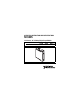
OPERATING INSTRUCTIONS AND SPECIFICATIONS NI 9425 32-Channel, 24 V Sinking Digital Input Module Français Deutsch ni.
This document describes how to use the National Instruments 9425 and includes specifications and pin assignments for the NI 9425. Visit ni.com/info and enter rdsoftwareversion to determine which software you need for the modules you are using. For information about installing, configuring, and programming the system, refer to the system documentation. Visit ni.com/info and enter cseriesdoc for information about C Series documentation.
Safety Guidelines Operate the NI 9425 only as described in these operating instructions. This icon denotes that the component may be hot. Touching this component may result in bodily injury. Hot Surface Safety Guidelines for Hazardous Voltages If hazardous voltages are connected to the module, take the following precautions. A hazardous voltage is a voltage greater than 42.4 Vpk or 60 VDC to earth ground.
When module terminals are hazardous voltage LIVE (>42.4 Vpk/60 VDC), you must ensure that devices and circuits connected to the module are properly insulated from human contact. Caution Safety Guidelines for Hazardous Locations The NI 9425 is suitable for use in Class I, Division 2, Groups A, B, C, D, T4 hazardous locations; Class I, Zone 2, AEx nC IIC T4, and Ex nC IIC T4 hazardous locations; and nonhazardous locations only.
For Zone 2 applications, install the system in an enclosure rated to at least IP 54 as defined by IEC 60529 and EN 60529. Caution Caution For Zone 2 applications, connected signals must be within the following limit: Capacitance .......................... 0.03 μF max Special Conditions for Hazardous Locations Use in Europe This equipment has been evaluated as EEx nC IIC T4 equipment under DEMKO Certificate No. 03 ATEX 0324020X.
Special Conditions for Marine Applications Some modules are Lloyd’s Register (LR) Type Approved for marine applications. To verify Lloyd’s Register certification, visit ni.com/certification and search for the LR certificate, or look for the Lloyd’s Register mark on the module. To meet radio frequency emission requirements for marine applications, use shielded cables and install the system in a metal enclosure.
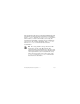
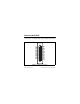
Connecting the NI 9425 The NI 9425 has a 37-pin DSUB connector that provides connections for 32 simultaneously-sampled digital input channels. DI16 DI17 DI18 DI19 DI20 DI21 DI22 DI23 COM COM DI24 DI25 DI26 DI27 DI28 DI29 DI30 DI31 20 21 22 23 24 25 26 27 28 29 30 31 32 33 34 35 36 37 1 2 3 4 5 6 7 8 9 10 11 12 13 14 15 16 17 18 19 DI0 DI1 DI2 DI3 DI4 DI5 DI6 DI7 COM COM DI8 DI9 DI10 DI11 DI12 DI13 DI14 DI15 NC Figure 1. NI 9425 Pin Assignments © National Instruments Corp.
Each channel has a DI pin to which you can connect a digital input signal. The NI 9425 has four common pins, COM, that are internally connected to the isolated reference of the module. The NI 9425 has sinking inputs, meaning that when the device drives a current or applies a voltage to the DI pin, the pin provides a path to COM for the current or voltage. The NI 9425 internally limits current signals connected to DI. For more information about input current levels, refer to the Specifications section.
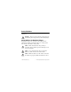
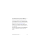
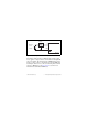
Sourcing-Output Device DI External + Power Supply _ COM NI 9425 Figure 2. Connecting a Device to the NI 9425 (Three-Wire Device Shown) The NI 9425 channel registers as ON when the sourcing-output device applies a voltage or drives a current that is in the input ON range to the DI pin. The channel registers as OFF when the device applies a voltage or drives a current that is in the input OFF range to the DI pin. If no device is connected to the DI pin, the channel registers as OFF.
Sleep Mode This module supports a low-power sleep mode. Support for sleep mode at the system level depends on the chassis that the module is plugged into. Refer to the chassis manual for information about support for sleep mode. If the chassis supports sleep mode, refer to the software help for information about enabling sleep mode. Visit ni.com/info and enter cseriesdoc for information about C Series documentation. Typically, when a system is in sleep mode, you cannot communicate with the modules.
Specifications The following specifications are typical for the range –40 to 70 °C unless otherwise noted. All voltages are relative to COM unless otherwise noted. Input Characteristics Number of channels.......................... 32 digital input channels Input type .......................................... Sinking Digital logic levels OFF state Input voltage ........................ ≤5 V Input current......................... ≤150 μA ON state Input voltage ........................ ≥10 V Input current...
I/O protection Input voltage 8 channels ............................ 60 VDC max 32 channels .......................... 30 VDC max Reverse-biased voltage 8 channels ............................ –60 VDC max 32 channels .......................... –30 VDC max Hold time1 ......................................... 0 μs min Setup time2 ........................................ 1 μs min Update/transfer time3 cRIO-9151 R Series Expansion chassis....................... 8 μs max All other chassis .......................
MTBF ............................................... 1,256,699 hours at 25 °C; Bellcore Issue 2, Method 1, Case 3, Limited Part Stress Method Note Contact NI for Bellcore MTBF specifications at other temperatures or for MIL-HDBK-217F specifications. Power Requirements Power consumption from chassis Active mode ............................... 410 mW max Sleep mode ................................. 0.5 mW max Thermal dissipation (at 70 °C) Active mode ............................... 1.45 W max Sleep mode ...
Safety Safety Voltages Connect only voltages that are within the following limits. Channel-to-COM .............................. 60 VDC max Isolation Channel-to-channel .................... None Channel-to-earth ground Continuous ........................... 60 VDC, Measurement Category I Withstand .............................
Caution Do not connect the NI 9425 to signals or use for measurements within Measurement Categories II, III, or IV. Hazardous Locations U.S. (UL) .......................................... Class I, Division 2, Groups A, B, C, D, T4; Class I, Zone 2, AEx nC IIC T4 Canada (C-UL) ................................. Class I, Division 2, Groups A, B, C, D, T4; Class I, Zone 2, Ex nC IIC T4 Europe (DEMKO).............................
Note For UL and other safety certifications, refer to the product label or the Online Product Certification section.
CE Compliance This product meets the essential requirements of applicable European Directives as follows: • 2006/95/EC; Low-Voltage Directive (safety) • 2004/108/EC; Electromagnetic Compatibility Directive (EMC) Online Product Certification Refer to the product Declaration of Conformity (DoC) for additional regulatory compliance information. To obtain product certifications and the DoC for this product, visit ni.
Operating shock (IEC 60068-2-27).............................. 30 g, 11 ms half sine, 50 g, 3 ms half sine, 18 shocks at 6 orientations Environmental National Instruments C Series modules are intended for indoor use only but may be used outdoors if installed in a suitable enclosure. Refer to the manual for the chassis you are using for more information about meeting these specifications. Operating temperature (IEC 60068-2-1, IEC 60068-2-2) .....
Maximum altitude............................. 2,000 m Pollution Degree (IEC 60664) .......... 2 Environmental Management NI is committed to designing and manufacturing products in an environmentally responsible manner. NI recognizes that eliminating certain hazardous substances from our products is beneficial to the environment and to NI customers. For additional environmental information, refer to the NI and the Environment Web page at ni.com/environment.
⬉ᄤֵᙃѻક∵ᶧࠊㅵ⧚ࡲ⊩ ˄Ё RoHS˅ Ёᅶ᠋ National Instruments ヺড়Ё⬉ᄤֵᙃ ѻકЁ䰤ࠊՓ⫼ᶤѯ᳝ᆇ⠽䋼ᣛҸ (RoHS)DŽ݇Ѣ National Instruments Ё RoHS ড়㾘ᗻֵᙃˈ䇋ⱏᔩ ni.com/environment/rohs_chinaDŽ (For information about China RoHS compliance, go to ni.com/ environment/rohs_china.) Where to Go for Support The National Instruments Web site is your complete resource for technical support. At ni.
telephone support outside the United States, contact your local branch office: Australia 1800 300 800, Austria 43 662 457990-0, Belgium 32 (0) 2 757 0020, Brazil 55 11 3262 3599, Canada 800 433 3488, China 86 21 5050 9800, Czech Republic 420 224 235 774, Denmark 45 45 76 26 00, Finland 358 (0) 9 725 72511, France 01 57 66 24 24, Germany 49 89 7413130, India 91 80 41190000, Israel 972 3 6393737, Italy 39 02 41309277, Japan 0120-527196, Korea 82 02 3451 3400, Lebanon 961 (0) 1 33 28 28, Malaysia 1800 887710,
National Instruments, NI, ni.com, and LabVIEW are trademarks of National Instruments Corporation. Refer to the Terms of Use section on ni.com/legal for more information about National Instruments trademarks. Other product and company names mentioned herein are trademarks or trade names of their respective companies. For patents covering National Instruments products/technology, refer to the appropriate location: Help»Patents in your software, the patents.