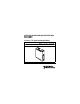
OPERATING INSTRUCTIONS AND SPECIFICATIONS NI 9401 8-Channel, TTL Digital Input/Output Module Français Deutsch ni.
This document describes how to use the National Instruments 9401 and includes specifications and pin assignments for the NI 9401. Visit ni.com/info and enter rdsoftwareversion to determine which software you need for the modules you are using. For information about installing, configuring, and programming the system, refer to the system documentation. Visit ni.com/info and enter cseriesdoc for information about C Series documentation.
Safety Guidelines Operate the NI 9401 only as described in these operating instructions. This icon denotes that the component may be hot. Touching this component may result in bodily injury. Hot Surface Safety Guidelines for Hazardous Locations The NI 9401 is suitable for use in Class I, Division 2, Groups A, B, C, D, T4 hazardous locations; Class I, Zone 2, AEx nC IIC T4, and Ex nC IIC T4 hazardous locations; and nonhazardous locations only.
Substitution of components may impair suitability for Class I, Division 2. Caution For Zone 2 applications, install the system in an enclosure rated to at least IP 54 as defined by IEC 60529 and EN 60529. Caution Caution For Zone 2 applications, connected signals must be within the following limit: Capacitance .......................... 0.2 μF max Special Conditions for Hazardous Locations Use in Europe This equipment has been evaluated as EEx nC IIC T4 equipment under DEMKO Certificate No.
Special Conditions for Marine Applications Some modules are Lloyd’s Register (LR) Type Approved for marine applications. To verify Lloyd’s Register certification, visit ni.com/certification and search for the LR certificate, or look for the Lloyd’s Register mark on the module. To meet radio frequency emission requirements for marine applications, use shielded cables and install the system in a metal enclosure.
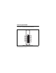
Connecting the NI 9401 The NI 9401 has a 25-pin DSUB connector that provides connections for eight digital input/output channels. DIO0 NC DIO1 DIO2 NC DIO3 DIO4 NC DIO5 DIO6 NC DIO7 14 1 15 2 16 3 17 4 18 5 19 6 20 7 21 8 9 22 10 23 11 24 12 25 13 COM NC COM COM NC COM COM NC COM COM NC COM COM Figure 1. NI 9401 Pin Assignments NI 9401 Operating Instructions and Specifications 6 ni.
Each channel has a DIO pin to which you can connect a digital input or output device. The eight DIO channels are internally referenced to COM, so you can use any of the nine COM lines as a reference for the external signal. The DIO channels are grouped in two ports, one containing channels 0, 1, 2, and 3, and one containing channels 4, 5, 6, and 7. You can independently configure each digital port in software for input or output. Note that all four channels in the port must share the same line direction.
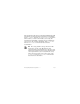
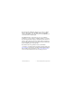
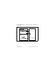
Figure 2 illustrates how to connect an SPI device to the NI 9401. In this example, the three channels assigned to output signals are on one port and the channel assigned to an input signal is on the other port. SS DIO3:0 Configured for Output SCLK MOSI MISO DIO7:4 Configured for Input SPI Device NI 9401 Figure 2. Connecting an SPI Device to the NI 9401 NI 9401 Operating Instructions and Specifications 8 ni.
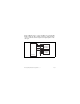
Figure 3 illustrates how to connect several types of digital devices to the NI 9401. DIO0 as Input Dev 1 TTL Signal DIO1 as Input +5 V Dev 2 +5 V LED COM DIO7 as Output NI 9401 Dev 3 Figure 3. Connecting Digital Devices to the NI 9401 © National Instruments Corp.
Overcurrent Protection Overcurrent protection on the NI 9401 allows only a specified amount of current for switching DIO channels or sourcing the output load. If the NI 9401 goes into an overcurrent state, by exceeding the specified maximum switching frequency or the output load, the module power supply begins to drop in voltage until it completely turns off or the overcurrent condition is removed.
Sleep Mode This module supports a low-power sleep mode. Support for sleep mode at the system level depends on the chassis that the module is plugged into. Refer to the chassis manual for information about support for sleep mode. If the chassis supports sleep mode, refer to the software help for information about enabling sleep mode. Visit ni.com/info and enter cseriesdoc for information about C Series documentation. Typically, when a system is in sleep mode, you cannot communicate with the modules.
Specifications The following specifications are typical for the range –40 to 70 °C unless otherwise noted. All voltages are relative to COM unless otherwise noted. Input/Output Characteristics Number of channels.......................... 8 DIO channels Default power-on line direction ........ Input Input/output type............................... TTL, single-ended NI 9401 Operating Instructions and Specifications 12 ni.
Digital logic levels Input Voltage ................................. 5.25 V max High, VIH.............................. 2 V min Low, VIL ............................... 0.8 V max Output High, VOH............................. 5.25 V max Sourcing 100 μA ........... 4.7 V min Sourcing 2 mA............... 4.3 V min Low, VOL Sinking 100 μA ............. 0.1 V max Sinking 2 mA................. 0.4 V max © National Instruments Corp.
Maximum input signal switching frequency by number of input channels, per channel 8 input channels.......................... 9 MHz 4 input channels.......................... 16 MHz 2 input channels.......................... 30 MHz Maximum output signal switching frequency by number of output channels with an output load of 1 mA, 50 pF, per channel 8 output channels........................ 5 MHz 4 output channels........................ 10 MHz 2 output channels........................
MTBF ............................................... 1,244,763 hours at 25 °C; Bellcore Issue 2, Method 1, Case 3, Limited Part Stress Method Note Contact NI for Bellcore MTBF specifications at other temperatures or for MIL-HDBK-217F specifications. Power Requirements Power consumption from chassis Active mode ............................... 580 mW max Sleep mode ................................. 1 mW max Thermal dissipation (at 70 °C) Active mode ............................... 580 mW max Sleep mode .....
Safety Maximum Voltage1 Connect only voltages that are within the following limits. Channel-to-COM .............................. ±30 V max on one channel at a time, Measurement Category I Isolation Voltages Channel-to-channel........................... None Channel-to-earth ground Continuous ................................. 60 VDC, Measurement Category I Withstand....................................
supply system that powers equipment. This category is for measurements of voltages from specially protected secondary circuits. Such voltage measurements include signal levels, special equipment, limited-energy parts of equipment, circuits powered by regulated low-voltage sources, and electronics. Caution Do not connect the NI 9401 to signals or use for measurements within Measurement Categories II, III, or IV.
Hazardous Locations U.S. (UL) .......................................... Class I, Division 2, Groups A, B, C, D, T4; Class I, Zone 2, AEx nC IIC T4 Canada (C-UL) ................................. Class I, Division 2, Groups A, B, C, D, T4; Class I, Zone 2, Ex nC IIC T4 Europe (DEMKO)............................. EEx nC IIC T4 Environmental National Instruments C Series modules are intended for indoor use only but may be used outdoors if installed in a suitable enclosure.
Operating humidity (IEC 60068-2-56).............................. 10 to 90% RH, noncondensing Storage humidity (IEC 60068-2-56).............................. 5 to 95% RH, noncondensing Maximum altitude............................. 2,000 m Pollution Degree (IEC 60664) .......... 2 Shock and Vibration To meet these specifications, you must panel mount the system. Operating vibration Random (IEC 60068-2-64)......... 5 grms, 10 to 500 Hz Sinusoidal (IEC 60068-2-6) .......
Electromagnetic Compatibility This product is designed to meet the requirements of the following standards of EMC for electrical equipment for measurement, control, and laboratory use: • EN 61326 EMC requirements; Industrial Immunity • EN 55011 Emissions; Group 1, Class A • CE, C-Tick, ICES, and FCC Part 15 Emissions; Class A Note For EMC compliance, operate this device with shielded cabling.
ni.com/certification, search by module number or product line, and click the appropriate link in the Certification column. Environmental Management National Instruments is committed to designing and manufacturing products in an environmentally responsible manner. NI recognizes that eliminating certain hazardous substances from our products is beneficial not only to the environment but also to NI customers. For additional environmental information, refer to the NI and the Environment Web page at ni.
⬉ᄤֵᙃѻક∵ᶧࠊㅵ⧚ࡲ⊩ ˄Ё RoHS˅ Ёᅶ᠋ National Instruments ヺড়Ё⬉ᄤֵᙃ ѻકЁ䰤ࠊՓ⫼ᶤѯ᳝ᆇ⠽䋼ᣛҸ (RoHS)DŽ݇Ѣ National Instruments Ё RoHS ড়㾘ᗻֵᙃˈ䇋ⱏᔩ ni.com/environment/rohs_chinaDŽ (For information about China RoHS compliance, go to ni.com/ environment/rohs_china.) Where to Go for Support The National Instruments Web site is your complete resource for technical support. At ni.
telephone support outside the United States, contact your local branch office: Australia 1800 300 800, Austria 43 662 457990-0, Belgium 32 (0) 2 757 0020, Brazil 55 11 3262 3599, Canada 800 433 3488, China 86 21 5050 9800, Czech Republic 420 224 235 774, Denmark 45 45 76 26 00, Finland 358 (0) 9 725 72511, France 01 57 66 24 24, Germany 49 89 7413130, India 91 80 41190000, Israel 972 3 6393737, Italy 39 02 41309277, Japan 0120-527196, Korea 82 02 3451 3400, Lebanon 961 (0) 1 33 28 28, Malaysia 1800 887710,
National Instruments, NI, ni.com, and LabVIEW are trademarks of National Instruments Corporation. Refer to the Terms of Use section on ni.com/legal for more information about National Instruments trademarks. Other product and company names mentioned herein are trademarks or trade names of their respective companies. For patents covering National Instruments products, refer to the appropriate location: Help»Patents in your software, the patents.txt file on your media, or ni.com/patents.