OPERATING INSTRUCTIONS AND SPECIFICATIONS NI 9265 4-Channel, 0–20 mA, 16-Bit Analog Current Output Module Français Deutsch ni.
This document describes how to use the National Instruments 9265 and includes specifications and terminal assignments for the NI 9265. Visit ni.com/info and enter rdsoftwareversion to determine which software you need for the modules you are using. For information about installing, configuring, and programming the system, refer to the system documentation. Visit ni.com/info and enter cseriesdoc for information about C Series documentation.
This icon denotes that the component may be hot. Touching this component may result in bodily injury. Hot Surface Safety Guidelines for Hazardous Voltages If hazardous voltages are connected to the module, take the following precautions. A hazardous voltage is a voltage greater than 42.4 Vpk or 60 VDC to earth ground. Ensure that hazardous voltage wiring is performed only by qualified personnel adhering to local electrical standards.
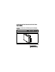
Figure 1 shows the NI 9932 connector backshell. Figure 1. NI 9932 Connector Backshell Safety Guidelines for Hazardous Locations The NI 9265 is suitable for use in Class I, Division 2, Groups A, B, C, D, T4 hazardous locations; Class I, Zone 2, AEx nC IIC T4, and Ex nC IIC T4 hazardous locations; and nonhazardous locations only. Follow these guidelines if you are installing the NI 9265 in a potentially explosive environment. Not following these guidelines may result in serious injury or death.
Caution Do not disconnect I/O-side wires or connectors unless power has been switched off or the area is known to be nonhazardous. Do not remove modules unless power has been switched off or the area is known to be nonhazardous. Caution Substitution of components may impair suitability for Class I, Division 2. Caution For Zone 2 applications, install the system in an enclosure rated to at least IP 54 as defined by IEC 60529 and EN 60529.
Special Conditions for Hazardous Locations Use in Europe This equipment has been evaluated as EEx nC IIC T4 equipment under DEMKO Certificate No. 03 ATEX 0324020X. Each module is marked II 3G and is suitable for use in Zone 2 hazardous locations. If you are using the NI 9265 in Gas Group IIC hazardous locations or in ambient temperatures of –40 °C ≤ Ta ≤ 70 °C, you must use the device in an NI chassis that has been evaluated as EEx nC IIC T4, Ex nA IIC T4, or Ex nL IIC T4 equipment.
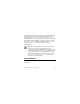
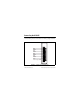
Connecting the NI 9265 The NI 9265 has a 10-terminal, detachable screw-terminal connector that provides connections for 4 analog output channels. AO0 COM0 AO1 COM1 AO2 COM2 AO3 COM3 Vsup Power Supply COM 0 1 2 3 4 5 6 7 8 9 Figure 2. NI 9265 Terminal Assignments © National Instruments Corp.
The NI 9265 has four analog output channels, AO. Each channel has a common terminal, COM, that is internally connected to the isolated ground reference of the module. The 9265 also has a terminal for an external power supply, Vsup, and an external power supply common terminal, Power Supply COM. Each AO channel has a digital-to-analog converter (DAC) that produces a current signal. Each channel also has overvoltage and short-circuit protection.
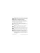
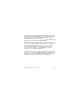
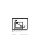
External Power + _ Supply Power Supply COM Vsup DC/DC Isolated DAC Protection AO Load COM NI 9265 Figure 3. Connecting a Load to the NI 9265 You must use 2-wire ferrules to create a secure connection when connecting more than one wire to a single terminal on the NI 9265. Note © National Instruments Corp.
You must connect an external power supply to the NI 9265. This power supply provides the current for the devices you connect to the module. Connect the positive lead of the power supply to the supply terminal, Vsup, and the negative lead of the power supply to Power Supply COM. When the module powers on, the channels output the startup current. Refer to the Specifications section for more information about startup current.
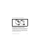
Figure 4. 10-Terminal Detachable Screw-Terminal Connector with Ferrule Sleep Mode This module supports a low-power sleep mode. Support for sleep mode at the system level depends on the chassis that the module is plugged into. Refer to the chassis manual for information about support for sleep mode. If the chassis supports sleep mode, refer to the software help for information about enabling sleep mode. © National Instruments Corp.
Visit ni.com/info and enter cseriesdoc for information about C Series documentation. Typically, when a system is in sleep mode, you cannot communicate with the modules. In sleep mode, the system consumes minimal power and may dissipate less heat than it does in normal mode. Refer to the Specifications section for more information about power consumption and thermal dissipation. Specifications The following specifications are typical for the range –40 to 70 °C unless otherwise noted.
Full-scale output current Minimum.................................... 20.1 mA Typical ........................................ 20.6 mA Maximum ................................... 21.0 mA Output range ..................................... 0 to 20 mA Compliance voltage .......................... 12 VDC max Maximum load.................................. 600 Ω Accuracy Percent of Reading (Gain Error) Percent of Range* (Offset Error) Calibrated, typ (25 °C, ±5 °C) 0.11% 0.
Stability Gain drift .................................... 30 ppm/°C Offset drift .................................. 45 ppm/°C External power supply voltage range (Vsup) .......................... 9–36 VDC Protection (AO, Vsup) Overvoltage ................................ ±40 V Short-circuit................................ Indefinitely Update time Number of Channels Update Time for R Series Expansion Chassis Update Time for Any Other Chassis One 3.5 μs 3 μs Two 6.5 μs 5 μs Three 9 μs 7.
Settling time (to 1 LSB) Full-scale step............................. 10 μs 1 mA step ................................... 5 μs Glitch energy .................................... Unmeasurable Monotonicity..................................... 16 bits DNL .................................................. 1 LSB max INL.................................................... ±16 LSB MTBF ...............................................
Thermal dissipation (at 70 °C) Active mode ............................... 1.5 W max Sleep mode ................................. 10 mW max Power consumption from external power supply Active mode ............................... 1.4 W max Sleep mode ................................. 10 mW Physical Characteristics If you need to clean the module, wipe it with a dry towel. Screw-terminal wiring ...................... 12 to 24 AWG copper conductor wire with 10 mm (0.39 in.
Safety Maximum Voltage1 Connect only voltages that are within the following limits. Channel-to-COM or Vsup-to-COM ... ±40 V max Isolation Voltages Channel-to-channel........................... No isolation between channels Channel-to-earth ground, Vsup-to-earth ground, or COM-to-earth ground Continuous ................................. 250 Vrms, Measurement Category II Withstand....................................
that provided by a standard wall outlet, for example, 115 V for U.S. or 230 V for Europe. Do not connect the NI 9265 to signals or use for measurements within Measurement Categories III or IV.
Canada (C-UL) ................................. Class I, Division 2, Groups A, B, C, D, T4; Class I, Zone 2, Ex nC IIC T4 Europe (DEMKO)............................. EEx nC IIC T4 Environmental National Instruments C Series modules are intended for indoor use only but may be used outdoors if installed in a suitable enclosure. Refer to the manual for the chassis you are using for more information about meeting these specifications. Operating temperature (IEC 60068-2-1, IEC 60068-2-2) .....
Storage humidity (IEC 60068-2-56).............................. 5 to 95% RH, noncondensing Maximum altitude............................. 2,000 m Pollution Degree (IEC 60664) .......... 2 Shock and Vibration To meet these specifications, you must panel mount the system and either affix ferrules to the ends of the terminal wires or use the NI 9932 backshell kit to protect the connections. Operating vibration Random (IEC 60068-2-64)......... 5 grms, 10 to 500 Hz Sinusoidal (IEC 60068-2-6) .......
Electromagnetic Compatibility This product is designed to meet the requirements of the following standards of EMC for electrical equipment for measurement, control, and laboratory use: • EN 61326 EMC requirements; Industrial Immunity • EN 55011 Emissions; Group 1, Class A • CE, C-Tick, ICES, and FCC Part 15 Emissions; Class A Note For EMC compliance, operate this device with shielded cabling.
ni.com/certification, search by module number or product line, and click the appropriate link in the Certification column. Environmental Management National Instruments is committed to designing and manufacturing products in an environmentally responsible manner. NI recognizes that eliminating certain hazardous substances from our products is beneficial not only to the environment but also to NI customers. For additional environmental information, refer to the NI and the Environment Web page at ni.
⬉ᄤֵᙃѻક∵ᶧࠊㅵ⧚ࡲ⊩ ˄Ё RoHS˅ Ёᅶ᠋ National Instruments ヺড়Ё⬉ᄤֵᙃ ѻકЁ䰤ࠊՓ⫼ᶤѯ᳝ᆇ⠽䋼ᣛҸ (RoHS)DŽ݇Ѣ National Instruments Ё RoHS ড়㾘ᗻֵᙃˈ䇋ⱏᔩ ni.com/environment/rohs_chinaDŽ (For information about China RoHS compliance, go to ni.com/ environment/rohs_china.) Calibration You can obtain the calibration certificate and information about calibration services for the NI 9265 at ni.com/calibration. Calibration interval ........................... 1 year © National Instruments Corp.
Where to Go for Support The National Instruments Web site is your complete resource for technical support. At ni.com/support you have access to everything from troubleshooting and application development self-help resources to email and phone assistance from NI Application Engineers. National Instruments corporate headquarters is located at 11500 North Mopac Expressway, Austin, Texas, 78759-3504. National Instruments also has offices located around the world to help address your support needs.
Korea 82 02 3451 3400, Lebanon 961 (0) 1 33 28 28, Malaysia 1800 887710, Mexico 01 800 010 0793, Netherlands 31 (0) 348 433 466, New Zealand 0800 553 322, Norway 47 (0) 66 90 76 60, Poland 48 22 3390150, Portugal 351 210 311 210, Russia 7 495 783 6851, Singapore 1800 226 5886, Slovenia 386 3 425 42 00, South Africa 27 0 11 805 8197, Spain 34 91 640 0085, Sweden 46 (0) 8 587 895 00, Switzerland 41 56 2005151, Taiwan 886 02 2377 2222, Thailand 662 278 6777, Turkey 90 212 279 3031, United Kingdom 44 (0) 1635 5
National Instruments, NI, ni.com, and LabVIEW are trademarks of National Instruments Corporation. Refer to the Terms of Use section on ni.com/legal for more information about National Instruments trademarks. Other product and company names mentioned herein are trademarks or trade names of their respective companies. For patents covering National Instruments products, refer to the appropriate location: Help»Patents in your software, the patents.txt file on your CD, or ni.com/patents.