OPERATING INSTRUCTIONS AND SPECIFICATIONS NI 9264 16-Channel, ±10 V, 16-Bit Analog Voltage Output Module Français Deutsch ni.
This document describes how to use the National Instruments 9264 and includes specifications and terminal assignments for the NI 9264. Visit ni.com/info and enter rdsoftwareversion to determine which software you need for the modules you are using. For information about installing, configuring, and programming the system, refer to the system documentation. Visit ni.com/info and enter cseriesdoc for information about C Series documentation.
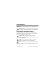
Safety Guidelines Operate the NI 9264 only as described in these operating instructions. This icon denotes that the component may be hot. Touching this component may result in bodily injury. Hot Surface Safety Guidelines for Hazardous Voltages If hazardous voltages are connected to the module, take the following precautions. A hazardous voltage is a voltage greater than 42.4 Vpk or 60 VDC to earth ground.
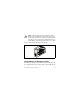
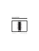
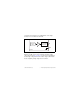
When module terminals are hazardous voltage LIVE (>42.4 Vpk/60 VDC), you must ensure that devices and circuits connected to the module are properly insulated from human contact. You must use the NI 9940 connector backshell kit to ensure that the terminals are not accessible. Caution Figure 1 shows the NI 9940 connector backshell. Figure 1.
Ex nA IIC T4 hazardous locations; and nonhazardous locations only. Follow these guidelines if you are installing the NI 9264 in a potentially explosive environment. Not following these guidelines may result in serious injury or death. Caution Do not disconnect I/O-side wires or connectors unless power has been switched off or the area is known to be nonhazardous. Do not remove modules unless power has been switched off or the area is known to be nonhazardous.
Special Conditions for Hazardous Locations Use in Europe This equipment has been evaluated as Ex nA IIC T4 equipment under DEMKO Certificate No. 07 ATEX 0626664X. Each module is marked II 3G and is suitable for use in Zone 2 hazardous locations. If you are using the NI 9264 in Gas Group IIC hazardous locations or in ambient temperatures of –40 °C ≤ Ta ≤ 70 °C, you must use the device in an NI chassis that has been evaluated as EEx nC IIC T4, Ex nA IIC T4, or Ex nL IIC T4 equipment.
Connecting the NI 9264 The NI 9264 has a 36-terminal detachable spring-terminal connector that provides connections for 16 analog output channels. AO0 AO1 AO2 AO3 AO4 AO5 AO6 AO7 AO8 AO9 AO10 AO11 AO12 AO13 AO14 AO15 COM COM 1 2 3 4 5 6 7 8 9 10 11 12 13 14 15 16 17 18 19 20 21 22 23 24 25 26 27 28 29 30 31 32 33 34 35 36 COM COM COM COM COM COM COM COM COM COM COM COM COM COM COM COM COM COM Figure 2. NI 9264 Terminal Assignments © National Instruments Corp.
Each channel of the NI 9264 has a terminal to which you can connect the positive lead of a load. Each channel also has a common terminal, COM, and there are four additional COM terminals at the bottom of the connector. All of the COM terminals are internally connected to the isolated ground reference of the module. When connecting a load to the NI 9264, connect the positive lead of the load to the AO terminal, and the ground of the load to a COM terminal.
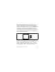
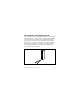
protection. Refer to Figure 4 for an illustration of the output circuitry for one channel of the NI 9264. Isolated DAC Overvoltage/ Short-Circuit Protection Amp AO COM NI 9264 Figure 4. Output Circuitry for One Channel of the NI 9264 When the module powers on, the channels output the startup voltage. Refer to the Specifications section for more information about startup voltage. Refer to the software help for information about configuring startup output states in software.
Connecting Wires to the NI 9264 Connector Use a flathead screwdriver with a blade smaller than 2.3 × 1.0 mm (0.09 × 0.04 in.) to connect wires to the detachable spring-terminal connector. Insert the screwdriver into a spring clamp activation slot and press a wire into the corresponding connector terminal, then remove the screwdriver to clamp the wire into the terminal. Refer to the Specifications section for more information about spring-terminal wiring.
Wiring for High-Vibration Applications If an application is subject to high vibration, National Instruments recommends that you use the NI 9940 backshell kit to protect the connections. Refer to Figure 1 for an illustration of the NI 9940 connector backshell. Sleep Mode This module supports a low-power sleep mode. Support for sleep mode at the system level depends on the chassis that the module is plugged into. Refer to the chassis manual for information about support for sleep mode.
Specifications The following specifications are typical for the range –40 to 70 °C unless otherwise noted. All voltages are relative to COM unless otherwise noted. Output Characteristics Number of channels.......................... 16 analog output channels DAC resolution ................................. 16 bits Type of DAC ..................................... String Output range Minimum.................................... ±10.35 V Typical ........................................ ±10.5 V Maximum ........
Power-down voltage ......................... 0 V1 Output impedance............................. 2.0 Ω Accuracy Percent of Reading (Gain Error) Percent of Range* (Offset Error) Calibrated, max (–40 to 70 °C) 0.15% 0.15% Calibrated, typ (25 °C) 0.05% 0.05% Uncalibrated, max (–40 to 70 °C) 0.6% 1.0% Uncalibrated, typ (25 °C) 0.2% 0.25% Measurement Conditions * Range equals 10.5 V Stability Gain drift .................................... 6 ppm/°C Offset drift ..................................
Protection Overvoltage ................................ ±27 V at 25 °C Short-circuit................................ Indefinitely Update time Number of Channels Update Time for cRIO-9151 R Series Expansion Chassis Update Time for All Other Chassis 1 3.7 μs min 3.1 μs min 2 6.6 μs min 5.3 μs min 3 9.4 μs min 7.5 μs min 16 47 μs min 37 μs min Noise ................................................. 500 μVrms Crosstalk ...........................................
Capacitive drive ................................ 1,500 pF max Monotonicity..................................... 16 bits DNL .................................................. +1 LSB max INL (endpoint) .................................. ±12 LSBs max MTBF ............................................... 595,509 hours at 25 °C; Bellcore Issue 2, Method 1, Case 3, Limited Part Stress Method Note Contact NI for Bellcore MTBF specifications at other temperatures or for MIL-HDBK-217F specifications.
Physical Characteristics If you need to clean the module, wipe it with a dry towel. Spring-terminal wiring...................... 18 to 28 AWG copper conductor wire with 7 mm (0.28 in.) of insulation stripped from the end Weight............................................... 156 g (5.5 oz) Safety Isolation Voltages Channel-to-channel........................... None Channel-to-earth ground Continuous ................................. 250 Vrms, Measurement Category II Withstand................................
Measurement Category II is for measurements performed on circuits directly connected to the electrical distribution system. This category refers to local-level electrical distribution, such as that provided by a standard wall outlet, for example, 115 V for U.S. or 230 V for Europe. Do not connect the NI 9264 to signals or use for measurements within Measurement Categories III or IV.
Hazardous Locations U.S. (UL) .......................................... Class I, Division 2, Groups A, B, C, D, T4; Class I, Zone 2, AEx nA IIC T4 Canada (C-UL) ................................. Class I, Division 2, Groups A, B, C, D, T4; Class I, Zone 2, Ex nA IIC T4 Europe (DEMKO)............................. Ex nA IIC T4 Environmental National Instruments C Series modules are intended for indoor use only but may be used outdoors if installed in a suitable enclosure.
Operating humidity (IEC 60068-2-56).............................. 10 to 90% RH, noncondensing Storage humidity (IEC 60068-2-56).............................. 5 to 95% RH, noncondensing Maximum altitude............................. 2,000 m Pollution Degree (IEC 60664) .......... 2 Shock and Vibration To meet these specifications, you must panel mount the system and use the NI 9940 backshell kit to protect the connections. Operating vibration Random (IEC 60068-2-64).........
Electromagnetic Compatibility This product is designed to meet the requirements of the following standards of EMC for electrical equipment for measurement, control, and laboratory use: • EN 61326 EMC requirements; Industrial Immunity • EN 55011 Emissions; Group 1, Class A • CE, C-Tick, ICES, and FCC Part 15 Emissions; Class A Note For EMC compliance, operate this device with shielded cabling.
Note Refer to the Declaration of Conformity (DoC) for this product for any additional regulatory compliance information. To obtain the DoC for this product, visit ni.com/certification, search by module number or product line, and click the appropriate link in the Certification column. Environmental Management National Instruments is committed to designing and manufacturing products in an environmentally responsible manner.
Waste Electrical and Electronic Equipment (WEEE) EU Customers At the end of their life cycle, all products must be sent to a WEEE recycling center. For more information about WEEE recycling centers and National Instruments WEEE initiatives, visit ni.com/ environment/weee.htm. ⬉ᄤֵᙃѻક∵ᶧࠊㅵ⧚ࡲ⊩ ˄Ё RoHS˅ Ёᅶ᠋ National Instruments ヺড়Ё⬉ᄤֵᙃ ѻકЁ䰤ࠊՓ⫼ᶤѯ᳝ᆇ⠽䋼ᣛҸ (RoHS)DŽ݇Ѣ National Instruments Ё RoHS ড়㾘ᗻֵᙃˈ䇋ⱏᔩ ni.com/environment/rohs_chinaDŽ (For information about China RoHS compliance, go to ni.
Where to Go for Support The National Instruments Web site is your complete resource for technical support. At ni.com/support you have access to everything from troubleshooting and application development self-help resources to email and phone assistance from NI Application Engineers. National Instruments corporate headquarters is located at 11500 North Mopac Expressway, Austin, Texas, 78759-3504. National Instruments also has offices located around the world to help address your support needs.
Korea 82 02 3451 3400, Lebanon 961 (0) 1 33 28 28, Malaysia 1800 887710, Mexico 01 800 010 0793, Netherlands 31 (0) 348 433 466, New Zealand 0800 553 322, Norway 47 (0) 66 90 76 60, Poland 48 22 3390150, Portugal 351 210 311 210, Russia 7 495 783 6851, Singapore 1800 226 5886, Slovenia 386 3 425 42 00, South Africa 27 0 11 805 8197, Spain 34 91 640 0085, Sweden 46 (0) 8 587 895 00, Switzerland 41 56 2005151, Taiwan 886 02 2377 2222, Thailand 662 278 6777, Turkey 90 212 279 3031, United Kingdom 44 (0) 1635 5