OPERATING INSTRUCTIONS AND SPECIFICATIONS NI 9229/9239 4-Channel, ±60/±10 V, 24-Bit Simultaneous, Channel-to-Channel Isolated Analog Input Modules Français Deutsch ni.
This document describes how to use the National Instruments 9229 and National Instruments 9239 and includes specifications and terminal assignments. In this document, the NI 9229 and NI 9239 are referred to inclusively as the NI 9229/9239. Visit ni.com/info and enter rdsoftwareversion to determine which software you need for the modules you are using. For information about installing, configuring, and programming the system, refer to the system documentation. Visit ni.
Safety Guidelines Operate the NI 9229/9239 only as described in these operating instructions. This icon denotes that the component may be hot. Touching this component may result in bodily injury. Hot Surface Safety Guidelines for Hazardous Voltages If hazardous voltages are connected to the module, take the following precautions. A hazardous voltage is a voltage greater than 42.4 Vpk or 60 VDC to earth ground.
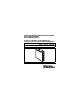
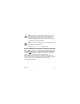
When module terminals are hazardous voltage LIVE (>42.4Vpk/60 VDC), you must ensure that devices and circuits connected to the module are properly insulated from human contact. You must use the NI 9971 connector backshell kit to ensure that the terminals are not accessible. Caution Figure 1 shows the NI 9971 connector backshell. Figure 1. NI 9971 Connector Backshell NI 9229/9239 4 ni.
Safety Guidelines for Hazardous Locations The NI 9229/9239 is suitable for use in Class I, Division 2, Groups A, B, C, D, T4 hazardous locations; Class I, Zone 2, AEx nA IIC T4, and Ex nA IIC T4 hazardous locations; and nonhazardous locations only. Follow these guidelines if you are installing the NI 9229/9239 in a potentially explosive environment. Not following these guidelines may result in serious injury or death.
For Zone 2 applications, install a protection device between the input signal and the NI 9229/9239 input terminal. The device must prevent the input channel-to-COM voltage from exceeding 85 V if there is a transient overvoltage condition. Caution Caution For Zone 2 applications, connected signals must be within the following limit: Capacitance .......................... 0.
Special Conditions for Marine Applications Some modules are Lloyd’s Register (LR) Type Approved for marine applications. To verify Lloyd’s Register certification, go to ni.com/certification and search for the LR certificate, or look for the Lloyd’s Register mark on the module. To meet radio frequency emission requirements for marine applications, use shielded cables and install the system in a metal enclosure.
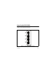
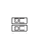
Connecting the NI 9229/9239 The NI 9229/9239 provides connections for four simultaneously sampled, isolated analog input channels. AI0+ AI0– 0 1 AI1+ AI1– 0 1 AI2+ AI2– 0 1 AI3+ AI3– 0 1 Figure 2. NI 9229/9239 Terminal Assignments NI 9229/9239 8 ni.
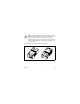
The NI 9229/9239 has four 2-terminal detachable screw-terminal connectors. You must use 2-wire ferrules to create a secure connection when connecting more than one wire to a single terminal on the NI 9229/9239. Note You can connect ground-referenced or floating signal sources to the NI 9229/9239. Connect the positive signal of the signal source to the AI+ terminal or connector, and connect the negative signal of the signal source to the AI– terminal or connector.
Signal Source + – AI+ AI– NI 9229/9239 Figure 3. Connecting a Grounded Signal Source to the NI 9229/9239 Signal Source AI+ + – AI– NI 9229/9239 Figure 4. Connecting a Floating Signal Source to the NI 9229/9239 NI 9229/9239 10 ni.
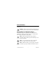
The NI 9229/9239 analog input channels are floating with respect to earth ground and each other. The incoming analog signal on each channel is conditioned, buffered, and then sampled by a 24-bit Delta-Sigma ADC. Each channel provides an independent signal path and ADC, enabling you to sample all four channels simultaneously. Refer to Figure 5 for an illustration of the circuitry for one channel. AI+ AI– Overvoltage Protection ADC Amplifier Prefilter NI 9229/9239 Figure 5.
Wiring for High-Vibration Applications If an application is subject to high vibration, National Instruments recommends that you either use ferrules to terminate wires to the detachable screw-terminal connector or use the NI 9971 backshell kit to protect the connections. Refer to Figure 6 for an illustration of using ferrules. Refer to Figure 1 for an illustration of the NI 9971 connector backshell. Figure 6. 2-Terminal Detachable Screw-Terminal Connector with Ferrule NI 9229/9239 12 ni.
Understanding NI 9229/9239 Filtering The NI 9229/9239 uses a combination of analog and digital filtering to provide an accurate representation of in-band signals while rejecting out-of-band signals. The filters discriminate between signals based on the frequency range, or bandwidth, of the signal. The three important bandwidths to consider are the passband, the stopband, and the alias-free bandwidth.
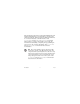
0.025 Gain (dB) 0.000 –0.025 –0.050 0 0.1 0.2 0.3 0.4 0.5 Frequency/Data Rate Figure 7. Typical Passband Flatness for the NI 9229/9239 NI 9229/9239 14 ni.
Stopband The filter significantly attenuates all signals above the stopband frequency. The primary goal of the filter is to prevent aliasing. Therefore, the stopband frequency scales precisely with the data rate. The stopband rejection is the minimum amount of attenuation applied by the filter to all signals with frequencies within the stopband. Alias-Free Bandwidth Any signal that appears in the alias-free bandwidth of the NI 9229/9239 is not an aliased artifact of signals at a higher frequency.
the modules must share a single master timebase source. Refer to the software help for information about configuring the master timebase source for the NI 9229/9239. Visit ni.com/info and enter cseriesdoc for information about C Series documentation. The following equation provides the available data rates of the NI 9229/9239: f M ÷ 256 fs = --------------------n where n is any integer from 1 to 31. However, the data rate must remain within the appropriate data rate range.
Sleep Mode This module supports a low-power sleep mode. Support for sleep mode at the system level depends on the chassis that the module is plugged into. Refer to the chassis manual for information about support for sleep mode. If the chassis supports sleep mode, refer to the software help for information about enabling sleep mode. Visit ni.com/info and enter cseriesdoc for information about C Series documentation. Typically, when a system is in sleep mode, you cannot communicate with the modules.
Specifications The following specifications are typical for the range –40 to 70 °C unless otherwise noted. All voltages are relative to the AI– signal on each channel unless otherwise noted. The specifications are the same for the NI 9229 and the NI 9239 unless otherwise noted. Input Characteristics Number of channels.......................... 4 analog input channels ADC resolution................................. 24 bits Type of ADC.....................................
Data rate range (fs) using external master timebase Minimum.................................... 390.625 S/s Maximum ................................... 51.2 kS/s f M ÷ 256 Data rates1 (fs) ................................... --------------------- , n = 1, 2, …, 31 n Input voltage ranges (AI+ to AI–)2 Module Nominal (V) Typical (V) Minimum (V) NI 9229 ±60 ±62.64 ±61.5 NI 9239 ±10 ±10.52 ±10.3 Overvoltage protection ..................... ±100 V Input coupling...................................
Accuracy, NI 9229 Percent of Reading (Gain Error) Percent of Range* (Offset Error) Calibrated max (–40 to 70 °C) ±0.13% ±0.05% Calibrated typ (25 °C, ±5 °C) ±0.03% ±0.008% Uncalibrated max (–40 to 70 °C) ±1.2% ±0.55% Uncalibrated typ (25 °C, ±5 °C) ±0.3% ±0.11% Measurement Conditions * Range equals 62.64 V NI 9229/9239 20 ni.
Accuracy, NI 9239 Percent of Reading (Gain Error) Percent of Range* (Offset Error) Calibrated max (–40 to 70 °C) ±0.13% ±0.06% Calibrated typ (25 °C, ±5 °C) ±0.03% ±0.008% Uncalibrated max (–40 to 70 °C) ±1.4% ±0.70% Uncalibrated typ (25 °C, ±5 °C) ±0.3% ±0.11% Measurement Conditions * Range equals 10.52 V Input noise NI 9229....................................... 320 μVrms NI 9239....................................... 70 μVrms Stability Gain drift ....................................
Post calibration gain match (ch-to-ch, 20 kHz)............................. 0.22 dB max Crosstalk (1 kHz).............................. –130 dB Phase mismatch (ch-to-ch) NI 9229....................................... 0.045°/kHz max NI 9239....................................... 0.075°/kHz max Phase mismatch (module-to-module, max) NI 9229....................................... 0.045°/kHz + 360°· fin/fM NI 9239....................................... 0.
Alias-free bandwidth ........................ 0.453 · fs –3 dB prefilter bandwidth (fs = 50 kS/s)...................................... 24.56 kHz CMRR (fin = 60 Hz) NI 9229....................................... 116 dB NI 9239....................................... 126 dB SFDR (1 kHz, –60 dBFS)................. –128 dBFS Total Harmonic Distortion (THD) 1 kHz, –1 dBFS .......................... –99 dB 1 kHz, –20 dBFS ........................ –105 dB MTBF ...............................................
Power Requirements Power consumption from chassis Active mode ............................... 740 mW max Sleep mode ................................. 25 μW max Thermal dissipation (at 70 °C) Active mode ............................... 760 mW max Sleep mode ................................. 16 mW max Physical Characteristics If you need to clean the module, wipe it with a dry towel. Screw-terminal wiring ...................... 16 to 28 AWG copper conductor wire with 7 mm (0.28 in.
Safety Safety Voltages Connect only voltages that are within the following limits. Channel-to-earth ground isolation Continuous ................................. 250 Vrms, Measurement Category II Withstand.................................... 2,300 Vrms, verified by a 5 s dielectric withstand test Channel-to-channel isolation Continuous ................................. 250 Vrms, Measurement Category II Withstand....................................
Measurement Category I is for measurements performed on circuits not directly connected to the electrical distribution system referred to as MAINS voltage. MAINS is a hazardous live electrical supply system that powers equipment. This category is for measurements of voltages from specially protected secondary circuits. Such voltage measurements include signal levels, special equipment, limited-energy parts of equipment, circuits powered by regulated low-voltage sources, and electronics.
Safety Standards This product is designed to meet the requirements of the following standards of safety for electrical equipment for measurement, control, and laboratory use: • IEC 61010-1, EN 61010-1 • UL 61010-1, CSA 61010-1 Note For UL and other safety certifications, refer to the product label or visit ni.com/certification, search for the module number or product line, and click the appropriate link in the Certification column. Hazardous Locations U.S. (UL) ..........................................
Environmental National Instruments C Series modules are intended for indoor use only but may be used outdoors if installed in a suitable enclosure. Refer to the manual for the chassis you are using for more information about meeting these specifications. Operating temperature (IEC 60068-2-1, IEC 60068-2-2) ..... –40 to 70 °C Storage temperature (IEC 60068-2-1, IEC 60068-2-2) ..... –40 to 85 °C Ingress protection.............................. IP 40 Operating humidity (IEC 60068-2-56).........................
Shock and Vibration To meet these specifications, you must panel mount the system and either affix ferrules to the ends of the terminal wires or use the NI 9971 backshell kit to protect the connections. Operating vibration Random (IEC 60068-2-64)......... 5 grms, 10 to 500 Hz Sinusoidal (IEC 60068-2-6) ....... 5 g, 10 to 500 Hz Operating shock (IEC 60068-2-27)..............................
Note For EMC compliance, operate this device with shielded cabling. CE Compliance This product meets the essential requirements of applicable European directives, as amended for CE marking, as follows: • 2006/95/EC; Low-Voltage Directive (safety) • 2004/108/EC; Electromagnetic Compatibility Directive (EMC) Note Refer to the Declaration of Conformity (DoC) for this product for any additional regulatory compliance information. To obtain the DoC for this product, visit ni.
For additional environmental information, refer to the NI and the Environment Web page at ni.com/environment. This page contains the environmental regulations and directives with which NI complies, as well as other environmental information not included in this document. Waste Electrical and Electronic Equipment (WEEE) EU Customers At the end of their life cycle, all products must be sent to a WEEE recycling center.
Calibration You can obtain the calibration certificate and information about calibration services for the NI 9229/9239 at ni.com/ calibration. Calibration interval ........................... 1 year Where to Go for Support The National Instruments Web site is your complete resource for technical support. At ni.com/support you have access to everything from troubleshooting and application development self-help resources to email and phone assistance from NI Application Engineers.
Australia 1800 300 800, Austria 43 662 457990-0, Belgium 32 (0) 2 757 0020, Brazil 55 11 3262 3599, Canada 800 433 3488, China 86 21 5050 9800, Czech Republic 420 224 235 774, Denmark 45 45 76 26 00, Finland 358 (0) 9 725 72511, France 01 57 66 24 24, Germany 49 89 7413130, India 91 80 41190000, Israel 972 3 6393737, Italy 39 02 41309277, Japan 0120-527196, Korea 82 02 3451 3400, Lebanon 961 (0) 1 33 28 28, Malaysia 1800 887710, Mexico 01 800 010 0793, Netherlands 31 (0) 348 433 466, New Zealand 0800 553 32
National Instruments, NI, ni.com, and LabVIEW are trademarks of National Instruments Corporation. Refer to the Terms of Use section on ni.com/legal for more information about National Instruments trademarks. Other product and company names mentioned herein are trademarks or trade names of their respective companies. For patents covering National Instruments products, refer to the appropriate location: Help»Patents in your software, the patents.txt file on your media, or ni.com/patents.