OPERATING INSTRUCTIONS AND SPECIFICATIONS NI 9233 4-Channel, ±5 V, 24-Bit IEPE Analog Input Module Français Deutsch ni.
This document describes how to use the National Instruments 9233 and includes specifications and connector assignments for the NI 9233. Visit ni.com/info and enter rdsoftwareversion to determine which software you need for the modules you are using. For information about installing, configuring, and programming the system, refer to the system documentation. Visit ni.com/info and enter cseriesdoc for information about C Series documentation.
Safety Guidelines Operate the NI 9233 only as described in these operating instructions. This icon denotes that the component may be hot. Touching this component may result in bodily injury. Hot Surface Safety Guidelines for Hazardous Locations The NI 9233 is suitable for use in Class I, Division 2, Groups A, B, C, D, T4 hazardous locations; Class I, Zone 2, AEx nC IIC T4, and Ex nC IIC T4 hazardous locations; and nonhazardous locations only.
Substitution of components may impair suitability for Class I, Division 2. Caution For Zone 2 applications, install the system in an enclosure rated to at least IP 54 as defined by IEC 60529 and EN 60529. Caution Caution For Zone 2 applications, connected signals must be within the following limit: Capacitance .......................... 0.2 μF max Special Conditions for Hazardous Locations Use in Europe This equipment has been evaluated as EEx nC IIC T4 equipment under DEMKO Certificate No.
Special Conditions for Marine Applications Some modules are Lloyd’s Register (LR) Type Approved for marine applications. To verify Lloyd’s Register certification, visit ni.com/certification and search for the LR certificate, or look for the Lloyd’s Register mark on the module. To meet radio frequency emission requirements for marine applications, use shielded cables and install the system in a metal enclosure.
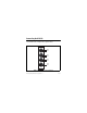
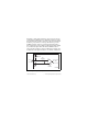
Connecting the NI 9233 The NI 9233 has four BNC connectors that provide connections for four simultaneously sampled analog input channels. AI0+ AI0– AI1+ AI1– AI2+ AI2– AI3+ AI3– Figure 1. NI 9233 Connector Assignments NI 9233 Operating Instructions and Specifications 6 ni.
Each channel has a BNC connector to which you can connect an Integrated Electronic Piezoelectric (IEPE) sensor. The center pin of the connector, AI+, provides the DC excitation and the AC signal connection. The shell of the connector, AI–, provides the excitation return path and the AC signal ground reference. You can connect ground-referenced or floating IEPE sensors to the NI 9233. You can avoid picking up ground noise by using a floating connection.
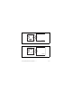
AI+ IEPE Sensor + – NI 9233 AI– Figure 2. Connecting a Grounded IEPE Sensor to the NI 9233 IEPE Sensor AI+ + – NI 9233 AI– Figure 3. Connecting a Floating IEPE Sensor to the NI 9233 NI 9233 Operating Instructions and Specifications 8 ni.
The NI 9233 analog input channels are referenced to the chassis ground through a 50 Ω resistor. To minimize ground noise, make sure that the chassis ground is connected to the earth ground. Each channel is protected from overvoltages. The NI 9233 provides an IEPE excitation current for each input signal. The signal is AC-coupled, buffered, and conditioned. The signal is then sampled by a 24-bit Delta-Sigma ADC. The NI 9233 IEPE excitation current and AC coupling are always enabled.
The NI 9233 also has TEDS circuitry. For more information about TEDS, visit ni.com/info and enter rdteds. Understanding NI 9233 Filtering The NI 9233 uses a combination of analog and digital filtering to provide an accurate representation of in-band signals while rejecting out-of-band signals. The filters discriminate between signals based on the frequency range, or bandwidth, of the signal. The three important bandwidths to consider are the passband, the stopband, and the alias-free bandwidth.
frequency depends on the data rate. Figure 5 shows typical passband flatness for data rates above 25.65 kS/s and less than or equal to 25.65 kS/s. 0.025 Data Rate > 25.65 kS/s Gain (dB) 0.000 –0.025 Data Rate ≤ 25.65 kS/s –0.050 0 0.1 0.2 0.3 0.4 0.5 Frequency/Data Rate Figure 5. Typical Passband Flatness for the NI 9233 © National Instruments Corp.
The relative phases of these signals also have a frequency-dependent delay. The variation in the phase delay with frequency is called the phase nonlinearity. Figure 6 shows the phase nonlinearity for data rates above 25.65 kS/s and less than or equal to 25.65 kS/s. The phase nonlinearity scales directly with the oversample rate, so the two curves normalize the signal frequency to the data rate. NI 9233 Operating Instructions and Specifications 12 ni.
4 Phase Error (Degrees) Data Rate ≤ 25.65 kS/s 2 0 –2 Data Rate > 25.65 kS/s –4 0.00 0.05 0.10 0.15 0.20 0.25 0.30 0.35 0.40 0.45 Frequency/Data Rate Figure 6. Phase Nonlinearity of the NI 9233 © National Instruments Corp.
Stopband The filter significantly attenuates all signals above the stopband frequency. The primary goal of the filter is to prevent aliasing. Therefore, the stopband frequency scales precisely with the data rate. The stopband rejection is the minimum amount of attenuation applied by the filter to all signals with frequencies within the stopband. Alias-Free Bandwidth Any signal that appears in the alias-free bandwidth of the NI 9233 is not an aliased artifact of signals at a higher frequency.
share a single master timebase source. Refer to the software help for information about configuring the master timebase source for the NI 9233. Visit ni.com/info and enter cseriesdoc for information about C Series documentation. The following equations provide the available data rates of the NI 9233: f M ÷ 256 When fs is ≤ 25.65 kS/s, fs = --------------------n where n is any integer from 2 to 25. f M ÷ 128 When fs is > 25.65 kS/s, fs = --------------------n where n is any integer from 2 to 3.
Note The cRIO-9151 R Series Expansion chassis does not support sharing timebases between modules. Sleep Mode This module supports a low-power sleep mode. Support for sleep mode at the system level depends on the chassis that the module is plugged into. Refer to the chassis manual for information about support for sleep mode. If the chassis supports sleep mode, refer to the software help for information about enabling sleep mode. Visit ni.
Specifications The following specifications are typical for the range –40 to 70 °C unless otherwise noted. Input Characteristics Number of channels.......................... 4 analog input channels ADC resolution................................. 24 bits Type of ADC..................................... Delta-Sigma (with analog prefiltering) Sampling mode ................................. Simultaneous Internal master timebase (fM) Frequency ................................... 12.8 MHz Accuracy...............
Data rates1 (fs) f M ÷ 256 fs ≤ 25.65 kS/s............................. --------------------- , n = 2, 3, ..., 25 n f M ÷ 128 fs > 25.65 kS/s ............................ --------------------- , n = 2, 3 n Input coupling................................... AC AC cutoff frequency –3 dB .......................................... 0.5 Hz typ –0.1 dB....................................... 4.2 Hz max 1 The data rate must remain within the appropriate data rate range.
AC cutoff frequency response 0.5 Gain (dB) 0.0 –0.5 –1.0 0 1 2 3 5 4 6 7 8 9 10 Frequency (Hz) Input range ........................................ ±5 V AC voltage full-scale range Minimum.................................... ±5 Vpk Typical ........................................ ±5.4 Vpk Maximum ................................... ±5.8 Vpk © National Instruments Corp.
Common-mode voltage range (AI– to earth ground) ........................ ±2 V max IEPE excitation current Minimum.................................... 2.0 mA Typical ........................................ 2.2 mA IEPE compliance voltage.................. 19 V max Use the following equation to make sure that your configuration meets the IEPE compliance voltage range. Vcommon-mode + Vbias ±Vfull-scale must be 0 to 19.
Overvoltage protection (with respect to chassis ground) For an IEPE sensor connected to AI+ and AI– ........................... ±30 V For a low-impedance source connected to AI+ and AI– .......... –6 to 30 V Input delay ≤25.65 kS/s ................................ 12.8/fs + 3 μs >25.65 kS/s ................................ 9.8/fs + 3 μs Accuracy (–40 to 70 °C) Calibrated typ ............................. ±0.1 dB Calibrated max ........................... ±0.3 dB Uncalibrated max ....................... ±0.
Channel-to-channel matching Gain Typical.................................. 0.07 dB Maximum............................. 0.27 dB Phase ( fin in kHz) ....................... fin · 0.077° + 0.067° Passband Flatness (pk-to-pk max) fs ≤25.65 kS/s....................... 0.05 dB (10 Hz to 0.45 · fs) fs >25.65 kS/s....................... 0.05 dB (10 Hz to 0.42 · fs) Phase nonlinearity fs ≤25.65 kS/s....................... ±3.4° (10 Hz to 0.45 · fs) fs >25.65 kS/s....................... ±1.3° (20 Hz to 0.
Crosstalk (fin = 1 kHz) Paired channels (0 and 1, 2 and 3)........................ –100 dB Nonpaired channels .................... –110 dB CMRR ( fin ≤ 1 kHz) Minimum.................................... 44 dB Typical ........................................ 56 dB SFDR ( fin = 1 kHz, –60 dBFS) ........ 120 dB Idle channel noise and noise density Idle Channel Noise Noise density 50 kS/s 25 kS/s 2 kS/s 95 dBFS 98 dBFS 102 dBFS 400 nV/√Hz 400 nV/√Hz 900 nV/√Hz Input impedance Differential (AC) .......
Total harmonic distortion (THD) Input Amplitude 1 kHz, –40 to 70 °C 10 kHz, 25 to 70 °C 10 kHz, –40 to 25 °C –1 dBFS –90 dB –80 dB –80 dB –20 dBFS –95 dB –90 dB –80 dB Intermodulation distortion (–1 dBFS) DIN 250 Hz/8 kHz 4:1 amplitude ratio ..................... –80 dB CCIF 11 kHz/12 kHz 1:1 amplitude ratio ..................... –93 dB MTBF ...............................................
Power Requirements Power consumption from chassis Active mode ............................... 620 mW max Sleep mode ................................. 0.5 mW max Thermal dissipation (at 70 °C) Active mode ............................... 640 mW max Sleep mode ................................. 0.5 mW max Physical Characteristics If you need to clean the module, wipe it with a dry towel. Weight............................................... 173 g (6.
Hazardous Locations U.S. (UL) .......................................... Class I, Division 2, Groups A, B, C, D, T4; Class I, Zone 2, AEx nC IIC T4 Canada (C-UL) ................................. Class I, Division 2, Groups A, B, C, D, T4; Class I, Zone 2, Ex nC IIC T4 Europe (DEMKO).............................
Electromagnetic Compatibility This product meets the requirements of the following EMC standards for electrical equipment for measurement, control, and laboratory use: • EN 61326 (IEC 61326): Class A emissions; Industrial immunity • EN 55011 (CISPR 11): Group 1, Class A emissions • AS/NZS CISPR 11: Group 1, Class A emissions • FCC 47 CFR Part 15B: Class A emissions • ICES-001: Class A emissions Note For the standards applied to assess the EMC of this product, refer to the Online Product Certificati
CE Compliance This product meets the essential requirements of applicable European Directives as follows: • 2006/95/EC; Low-Voltage Directive (safety) • 2004/108/EC; Electromagnetic Compatibility Directive (EMC) Online Product Certification Refer to the product Declaration of Conformity (DoC) for additional regulatory compliance information. To obtain product certifications and the DoC for this product, visit ni.
Operating shock (IEC 60068-2-27).............................. 30 g, 11 ms half sine, 50 g, 3 ms half sine, 18 shocks at 6 orientations Environmental National Instruments C Series modules are intended for indoor use only but may be used outdoors if installed in a suitable enclosure. Refer to the manual for the chassis you are using for more information about meeting these specifications. Operating temperature (IEC 60068-2-1, IEC 60068-2-2) .....
Maximum altitude............................. 2,000 m Pollution Degree (IEC 60664) .......... 2 Environmental Management NI is committed to designing and manufacturing products in an environmentally responsible manner. NI recognizes that eliminating certain hazardous substances from our products is beneficial to the environment and to NI customers. For additional environmental information, refer to the NI and the Environment Web page at ni.com/environment.
⬉ᄤֵᙃѻક∵ᶧࠊㅵ⧚ࡲ⊩ ˄Ё RoHS˅ Ёᅶ᠋ National Instruments ヺড়Ё⬉ᄤֵᙃ ѻકЁ䰤ࠊՓ⫼ᶤѯ᳝ᆇ⠽䋼ᣛҸ (RoHS)DŽ݇Ѣ National Instruments Ё RoHS ড়㾘ᗻֵᙃˈ䇋ⱏᔩ ni.com/environment/rohs_chinaDŽ (For information about China RoHS compliance, go to ni.com/ environment/rohs_china.) Calibration You can obtain the calibration certificate and information about calibration services for the NI 9233 at ni.com/calibration. Calibration interval ........................... 1 year © National Instruments Corp.
Where to Go for Support The National Instruments Web site is your complete resource for technical support. At ni.com/support you have access to everything from troubleshooting and application development self-help resources to email and phone assistance from NI Application Engineers. National Instruments corporate headquarters is located at 11500 North Mopac Expressway, Austin, Texas, 78759-3504. National Instruments also has offices located around the world to help address your support needs.
Korea 82 02 3451 3400, Lebanon 961 (0) 1 33 28 28, Malaysia 1800 887710, Mexico 01 800 010 0793, Netherlands 31 (0) 348 433 466, New Zealand 0800 553 322, Norway 47 (0) 66 90 76 60, Poland 48 22 3390150, Portugal 351 210 311 210, Russia 7 495 783 6851, Singapore 1800 226 5886, Slovenia 386 3 425 42 00, South Africa 27 0 11 805 8197, Spain 34 91 640 0085, Sweden 46 (0) 8 587 895 00, Switzerland 41 56 2005151, Taiwan 886 02 2377 2222, Thailand 662 278 6777, Turkey 90 212 279 3031, United Kingdom 44 (0) 1635 5
National Instruments, NI, ni.com, and LabVIEW are trademarks of National Instruments Corporation. Refer to the Terms of Use section on ni.com/legal for more information about National Instruments trademarks. Other product and company names mentioned herein are trademarks or trade names of their respective companies. For patents covering National Instruments products/technology, refer to the appropriate location: Help»Patents in your software, the patents.