
Universal Analog Input Module Operating Instructions

© National Instruments Corp. 13 NI 9219 Operating Instructions
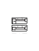
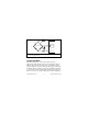
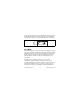
Figure 5. Input Circuitry for One Channel
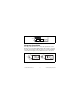
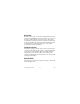
Voltage and Current Modes
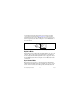
In Voltage and Current modes, connect the signal source to the
NI 9219 across the HI and LO terminals. The current is computed
from the voltage that the ADC measures across an internal shunt
resistor. Refer to Figure 6 for an illustration of the connections.
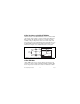
Figure 6. Connections in Voltage, Current, and Digital In Modes
Isolated
ADC
TEDS
1
2
+
–
CHx
3
6
NI 9219
FilterMUX
Current mode
HI
LO
ADC
I
R
SH
NI 9219
Voltage/Digital In modes
HI
LO
ADC
V
+
–
NI 9219