OPERATING INSTRUCTIONS NI 9219 4-Channel, 24-Bit, Universal Analog Input Module
These operating instructions describe how to use the National Instruments 9219. For information about installing, configuring, and programming the system, refer to the system documentation. Visit ni.com/info and enter the info code rdsoftwareversion to determine which software you need for the modules you are using. The safety guidelines and specifications in this document are specific to the NI 9219. The other components in the system might not meet the same safety ratings and specifications.
Safety Guidelines for Hazardous Voltages If hazardous voltages are connected to the module, take the following precautions. A hazardous voltage is a voltage greater than 42.4 Vpk or 60 VDC to earth ground. Ensure that hazardous voltage wiring is performed only by qualified personnel adhering to local electrical standards. Caution Caution Do not mix hazardous voltage circuits and human-accessible circuits on the same module.
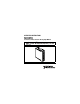
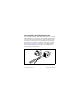
Figure 1 shows the NI 9972 connector backshell. Figure 1. NI 9972 Connector Backshell Safety Guidelines for Hazardous Locations The NI 9219 is suitable for use in Class I, Division 2, Groups A, B, C, D, T4 hazardous locations; Class I, Zone 2, AEx nC IIC T4 hazardous locations; and nonhazardous locations only. Follow these guidelines if you are installing the NI 9219 in a potentially explosive environment. Not following these guidelines may result in serious injury or death.
Caution Do not remove modules unless power has been switched off or the area is known to be nonhazardous. Substitution of components may impair suitability for Class I, Division 2. Caution For Zone 2 applications, install the system in an enclosure rated to at least IP 54 as defined by IEC 60529 and EN 60529. Caution Special Conditions for Marine Applications Some modules are Lloyd’s Register (LR) Type Approved for marine applications. To verify Lloyd’s Register certification, visit ni.
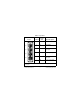
Wiring the NI 9219 The NI 9219 has four 6-terminal connectors that provide connections for four analog input channels. Connect the positive signal of the signal source to the positive input signal terminal (HI) and the negative signal of the signal source to the negative input signal terminal (LO). Use the excitation terminals if your sensor requires a separate excitation connection. Refer to Table 1 for the signal names and Table 2 for the terminal assignments for each mode.
Table 1. Signal Names Module Signal Name Terminal Ch 0 1 2 3 4 5 6 Ch 1 1 2 3 4 5 6 Ch 2 1 2 3 4 5 6 Ch 3 1 2 3 4 5 6 Signal Description 1 T+ TEDS Data 2 T– TEDS COM 3 EX+/HI* Positive excitation or input signal 4 HI Positive input signal 5 EX–/LO* Negative excitation or input signal 6 LO Negative input signal * Depending on the mode, terminals 3 and 5 are either the excitation signals or the input signals. © National Instruments Corp.
Table 2.
Connecting Wires to the NI 9219 Connectors Use a flathead screwdriver with a blade smaller than 2.3 × 1.0 mm (0.09 × 0.04 in.) to connect wires to the detachable spring-terminal connectors. Insert the screwdriver into a spring clamp activation slot and press a wire into the corresponding connector terminal, then remove the screwdriver to clamp the wire into the terminal. Refer to the Specifications section for more information about spring-terminal wiring.
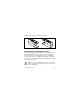
Wiring TEDS Channels The NI 9219 supports only Class II TEDS sensors. Connect the two TEDS lines to TEDS Data (T+) and TEDS COM (T–) and ensure that neither T+ nor T– is tied in common to any of the signal inputs (terminals 3 through 6) on the NI 9219. Visit ni.com/info and enter the info code rdteds for information about TEDS sensors. Grounding and Shielding Considerations You can connect ground-referenced or floating signal sources to the NI 9219.
Signal Source Twisted-Pair Wiring Shielding HI VSIG + – NI 9219 LO VSIG Ground Reference Figure 3. Connecting a Grounded Signal Source to the NI 9219 Signal Source Twisted-Pair Wiring Shielding HI VSIG + – LO NI 9219 Figure 4. Connecting a Floating Signal Source to the NI 9219 © National Instruments Corp.
NI 9219 Timing Options The NI 9219 supports four different timing options that are optimized for different types of applications by using different ADC conversion times. High Speed is optimized for high speed at the expense of noise rejection, Best 60 Hz Rejection is optimized for rejection of 60 Hz noise, Best 50 Hz Rejection is optimized for rejection of 50 Hz noise, and High Resolution is optimized for maximum overall noise rejection and provides good rejection of 50 Hz and 60 Hz noise.
1 2 CHx 3 + – NI 9219 TEDS MUX Isolated ADC Filter 6 Figure 5. Input Circuitry for One Channel Voltage and Current Modes In Voltage and Current modes, connect the signal source to the NI 9219 across the HI and LO terminals. The current is computed from the voltage that the ADC measures across an internal shunt resistor. Refer to Figure 6 for an illustration of the connections. HI HI V + – ADC LO RSH I ADC LO NI 9219 NI 9219 Current mode Voltage/Digital In modes Figure 6.
4-Wire Resistance and 4-Wire RTD Modes 4-Wire Resistance and 4-Wire RTD modes source a current, which varies based on the resistance of the load, between the EX+ and EX– terminals. The measured resistance is computed from the resulting voltage reading. These modes are not affected by lead wire resistance because a negligible amount of current flows across the HI and LO terminals due to the high input impedance of the ADC. Refer to Figure 7 for an illustration of the connections.
lead wires have the same resistance. A gain of 2x is applied to the voltage across the negative lead wire and the ADC uses this voltage as the negative reference to cancel the resistance error across the positive lead wire. Refer to Figure 8 for an illustration of the connections. I RTD Wire EX+ Wire LO Wire I ADC EX– x2 I NI 9219 Figure 8.
for lead wire resistance. Refer to Figure 9 for an illustration of the connections. Wire HI Wire LO I ADC R I NI 9219 Figure 9. Connections in 2-Wire Resistance and Quarter-Bridge Modes Half-Bridge and Full-Bridge Modes Half-Bridge and Full-Bridge modes use the internal voltage excitation to set the input range of the ADC and return voltage readings that are proportional to the excitation level. The internal excitation voltage is nominally 2.5 V but it varies based on the resistance of the sensor.
Wire R1 EX+ R4 HI ADC LO R2 R3 1 Wire EX– NI 9219 1 The dotted line represents the portion of the circuit that is connected only in Full-Bridge mode. Figure 10. Connections in Half-Bridge and Full-Bridge Modes Thermocouple Mode In Thermocouple mode, connect the positive end of the thermocouple to HI and the negative end of the thermocouple to LO. This mode uses the ±125 mV range of the ADC to return a voltage reading. Use shielded cables and twisted pair wiring and ground the shielded cables.
environment and avoid placing heat sources near the module or its connectors. Refer to the Specifications section for more information about accuracy. The NI 9219 does not support open thermocouple detection. Refer to Figure 11 for an illustration of the connections. HI TC + – ADC LO NI 9219 Figure 11. Connections in Thermocouple Mode Digital In Mode Digital In mode has a 60 V unipolar threshold that you can set in software.
circuit is open, make sure no more than ±60 V is sourced across the switch. Open Contact mode is supported only in CompactRIO systems. Refer to Figure 12 for an illustration of the connections. HI ADC I LO NI 9219 Figure 12. Connections in Open Contact Mode Sleep Mode This module supports a low-power sleep mode. Support for sleep mode at the system level depends on the chassis that the module is plugged into. Refer to the chassis documentation for information about support for sleep mode.
Binary Data NI 9219 modules in the system return calibrated binary data when used in a CompactRIO chassis. For these modules, you can convert the data to engineering units in software. Refer to the software documentation for information about converting data. When used in a CompactDAQ chassis, NI 9219 modules automatically return the data in terms of engineering units. Refer to the software documentation for more information.
Input Characteristics Number of channels.......................... 4 analog input channels ADC resolution................................. 24 bits Type of ADC..................................... Delta-sigma (with analog prefiltering) Sampling mode ................................. Simultaneous Type of TEDS supported .................. IEEE 1451.
Mode Full-Bridge Nominal Range(s) ±62.5 mV/V, ±7.8 mV/V Actual Range(s) ±62.5 mV/V, ±7.8125 mV/V Digital In — 0–60 V Open Contact — 1.05 kΩ Conversion time, no channels in TC mode High speed.................................. 10 ms for all channels Best 60 Hz rejection ................... 110 ms for all channels Best 50 Hz rejection ................... 130 ms for all channels High resolution...........................
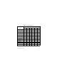
Input impedance Voltage and Digital In modes (±60 V, ±15 V, ±4 V) ..................... 1 MΩ Current mode.............................. < 40 Ω All other modes .......................... >1 GΩ Accuracy Gain Error (% of Reading) Offset Error (ppm of Range) Typ (25 °C, ±5 °C), Max (–40 to 70 °C) Mode, Range Voltage, ±60 V ±0.3, ±0.4 Voltage, ±15 V ±0.3, ±0.4 ±60, ±180 Voltage, ±4 V ±0.3, ±0.4 ±240, ±720 Voltage, ±1 V ±0.1, ±0.18 ±15, ±45 Voltage/Thermocouple, ±125 mV ±0.1, ±0.
Gain Error (% of Reading) Offset Error (ppm of Range) Typ (25 °C, ±5 °C), Max (–40 to 70 °C) Mode, Range 4-Wire and 3-Wire RTD, Pt 1000 ±0.1, ±0.5 ±240, ±640 4-Wire and 3-Wire RTD, Pt 100 ±0.1, ±0.5 ±2400, ±6400 Quarter-Bridge, 350 Ω ±0.1, ±0.5 ±2400, ±6400 Quarter-Bridge, 120 Ω ±0.1, ±0.5 ±2400, ±6400 Half-Bridge, ±500 mV/V ±0.03, ±0.07 ±300, ±450 Full-Bridge, ±62.5 mV/V ±0.03, ±0.08 ±300, ±1000 Full-Bridge, ±7.8 mV/V ±0.03, ±0.
Stability Gain Drift (ppm of Reading/°C) Offset Drift (ppm of Range/°C) Voltage, ±60 V ±20 ±0.2 Voltage, ±15 V ±20 ±0.8 Voltage, ±4 V ±20 ±3.2 Voltage, ±1 V ±10 ±0.2 Voltage/Thermocouple, ±125 mV ±10 ±1.6 Current, ±25 mA ±15 ±0.
Gain Drift (ppm of Reading/°C) Offset Drift (ppm of Range/°C) Full-Bridge, ±62.5 mV/V ±3 ±20 Full-Bridge, ±7.8 mV/V ±3 ±20 Mode, Range Input noise in ppm of Rangerms Conversion Time Mode, Range Best Best High 60 Hz 50 Hz resoHigh speed rejection rejection lution Voltage, ±60 V 7.6 1.3 1.3 0.5 Voltage, ±15 V 10.8 1.9 1.9 0.7 Voltage, ±4 V 10.8 2.7 2.7 1.3 Voltage, ±1 V 7.6 1.3 1.3 0.5 Voltage/Thermocouple, ±125 mV 10.8 1.9 1.9 1.0 Current, ±25 mA 10.8 1.9 1.9 1.
Conversion Time Mode, Range Best Best High 60 Hz 50 Hz resoHigh speed rejection rejection lution 4-Wire and 2-Wire Resistance, 10 kΩ 4.1 1.3 0.8 0.3 4-Wire and 2-Wire Resistance, 1 kΩ 7.1 1.8 1.2 0.7 4-Wire and 3-Wire RTD, Pt 1000 7.6 1.7 1.1 0.4 4-Wire and 3-Wire RTD, Pt 100 10.8 1.9 1.9 0.9 Quarter-Bridge, 350 Ω 5.4 1.0 1.0 0.7 Quarter-Bridge, 120 Ω 5.4 1.0 1.0 0.7 Half-Bridge, ±500 mV/V 3.8 0.5 0.5 0.2 Full-Bridge, ±62.5 mV/V 5.4 1.0 1.0 0.8 Full-Bridge, ±7.
Input bias current .............................. <1 nA INL.................................................... ±15 ppm CMRR (fin = 60 Hz) .......................... >100 dB NMRR Best 60 Hz rejection ................... 90 dB at 60 Hz Best 50 Hz rejection ................... 80 dB at 50 Hz High resolution........................... 65 dB at 50 Hz and 60 Hz Excitation level for Half-Bridge and Full-Bridge modes Mode Load Resistance (Ω) Excitation (V) Half-Bridge 700 2.5 Half-Bridge 240 2.
Excitation level for Resistance, RTD, and Quarter-Bridge modes Load Resistance (Ω) Excitation (mV) 120 50 350 150 1k 430 10 k 2200 MTBF ............................................... 384,716 hours at 25 °C; Bellcore Issue 6, Method 1, Case 3, Limited Part Stress Method Note Contact NI for Bellcore MTBF specifications at other temperatures or for MIL-HDBK-217F specifications. Power Requirements Power consumption from chassis Active mode ............................... 750 mW max Sleep mode ......
Thermal dissipation (at 70 °C) Active mode ............................... 625 mW max Sleep mode ................................. 25 μW max Physical Characteristics If you need to clean the module, wipe it with a dry towel. Spring-terminal wiring...................... 18 to 28 AWG copper conductor wire with 7 mm (0.28 in.) of insulation stripped from the end Weight............................................... 156 g (5.5 oz) Safety Safety Voltages Connect only voltages that are within these limits.
Channel-to-earth ground Continuous ........................... 250 VAC, Measurement Category II Withstand ............................. 2300 VAC, verified by a 5 s dielectric withstand test Measurement Category II is for measurements performed on circuits directly connected to the electrical distribution system. This category refers to local-level electrical distribution, such as that provided by a standard wall outlet, for example, 115 V for U.S. or 230 V for Europe.
by module number or product line, and click the appropriate link in the Certification column. Hazardous Locations U.S. (UL) .......................................... Class I, Division 2, Groups A, B, C, D, T4; Class I, Zone 2, AEx nC IIC T4 Environmental National Instruments C Series modules are intended for indoor use only but may be used outdoors if installed in a suitable enclosure.
Maximum altitude............................. 2,000 m Pollution Degree (IEC 60664) .......... 2 Shock and Vibration To meet these specifications, you must panel mount the system. Operating vibration Random (IEC 60068-2-34)......... 5 grms, 10 to 500 Hz Sinusoidal (IEC 60068-2-6) ....... 5 g, 10 to 500 Hz Operating shock (IEC 60068-2-27)..............................
Note For EMC compliance, operate this device with shielded cabling. CE Compliance This product meets the essential requirements of applicable European directives, as amended for CE markings, as follows: • 73/23/EEC; Low-Voltage Directive (safety) • 89/336/EEC; Electromagnetic Compatibility Directive (EMC) Note Refer to the Declaration of Conformity (DoC) for this product for any additional regulatory compliance information. To obtain the DoC for this product, visit ni.
Calibration You can obtain the calibration certificate and information about calibration services for the NI 9219 at ni.com/calibration. Calibration interval ........................... 1 year Where to Go for Support The National Instruments Web site is your complete resource for technical support. At ni.com/support you have access to everything from troubleshooting and application development self-help resources to email and phone assistance from NI Application Engineers.
Canada 800 433 3488, China 86 21 5050 9800, Czech Republic 420 224 235 774, Denmark 45 45 76 26 00, Finland 385 (0) 9 725 72511, France 01 57 66 24 24, Germany 49 89 7413130, India 91 80 41190000, Israel 972 3 6393737, Italy 39 02 413091, Japan 81 3 5472 2970, Korea 82 02 3451 3400, Lebanon 961 (0) 1 33 28 28, Malaysia 1800 887710, Mexico 01 800 010 0793, Netherlands 31 (0) 348 433 466, New Zealand 0800 553 322, Norway 47 (0) 66 90 76 60, Poland 48 22 3390150, Portugal 351 210 311 210, Russia 7 495 783 6851