OPERATING INSTRUCTIONS AND SPECIFICATIONS NI 9215 4-Channel, ±10 V, 16-Bit Simultaneous Analog Input Module Français Deutsch ni.
This document describes how to use the National Instruments 9215 and includes specifications and terminal assignments for the NI 9215. In this document, the NI 9215 with screw terminal and NI 9215 with BNC are referred to inclusively as the NI 9215. Visit ni.com/info and enter rdsoftwareversion to determine which software you need for the modules you are using. For information about installing, configuring, and programming the system, refer to the system documentation. Visit ni.
This icon denotes that the component may be hot. Touching this component may result in bodily injury. Hot Surface Safety Guidelines for Hazardous Voltages You can connect hazardous voltages only to the NI 9215 with screw terminal. Do not connect hazardous voltages to the NI 9215 with BNC. If hazardous voltages are connected to the module, take the following precautions. A hazardous voltage is a voltage greater than 42.4 Vpk or 60 VDC to earth ground.
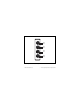
and circuits connected to the module are properly insulated from human contact. You must use the NI 9932 connector backshell kit to ensure that the terminals are not accessible. Figure 1 shows the NI 9932 connector backshell. Note You can use the NI 9932 connector backshell only with the NI 9215 with screw terminal. Figure 1. NI 9932 Connector Backshell NI 9215 Operating Instructions and Specifications 4 ni.
Safety Guidelines for Hazardous Locations The NI 9215 is suitable for use in Class I, Division 2, Groups A, B, C, D, and T4 hazardous locations; Class I, Zone 2, AEx nC IIC T4 and Ex nC IIC T4 hazardous locations; and nonhazardous locations only. Follow these guidelines if you are installing the NI 9215 in a potentially explosive environment. Not following these guidelines may result in serious injury or death.
Caution For Zone 2 applications, connected signals must be within the following limit: Capacitance .......................... 0.2 μF max Special Conditions for Hazardous Locations Use in Europe This equipment has been evaluated as EEx nC IIC T4 equipment under DEMKO Certificate No. 03 ATEX 0324020X. Each module is marked II 3G and is suitable for use in Zone 2 hazardous locations.
To meet radio frequency emission requirements for marine applications, use shielded cables and install the system in a metal enclosure. Suppression ferrites must be installed on power supply inputs near power entries to modules and controllers. Power supply and module cables must be separated on opposite sides of the enclosure, and must enter and exit through opposing enclosure walls. Caution © National Instruments Corp.
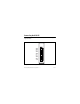
Connecting the NI 9215 The NI 9215 provides connections for four differential analog input channels. AI0+ AI0– AI1+ AI1– AI2+ AI2– AI3+ AI3– NC COM 0 1 2 3 4 5 6 7 8 9 Figure 2. Terminal Assignments of the NI 9215 with Screw Terminal NI 9215 Operating Instructions and Specifications 8 ni.
AI0+ AI0– AI1+ AI1– AI2+ AI2– AI3+ AI3– Figure 3. Connector Assignments of the NI 9215 with BNC © National Instruments Corp.
The NI 9215 with screw terminal has a 10-terminal detachable screw-terminal connector. The NI 9215 with BNC has four BNC connectors. Each channel of the NI 9215 has an AI+ terminal or shield to which you can connect the positive voltage signal, and an AI– terminal or shield to which you can connect the negative voltage signal. The NI 9215 with screw terminal also has a common terminal, COM, that is internally connected to the isolated ground reference of the module.
Connecting Differential Voltage Signals to the NI 9215 You can connect grounded or floating differential signals to the NI 9215. Connect the positive voltage signal to AI+ and the negative voltage signal to AI–. To connect grounded differential signals to the NI 9215 with screw terminal, you must also connect the signal reference to the COM terminal, as shown in Figure 4. AI+ Voltage Source + – AI– COM NI 9215 with Screw Terminal Figure 4.
To connect floating differential signals to the NI 9215 with screw terminal, you must connect the negative lead of the signal to COM through a 1 MΩ resistor to keep the voltage source within the common-mode voltage range, as shown in Figure 5. If the voltage source is outside of the common-mode range, then the NI 9215 does not read data accurately. The NI 9215 with BNC has internal circuitry that keeps the voltage source within the common-mode range.
Connecting Single-Ended Voltage Signals to the NI 9215 To connect single-ended voltage signals to the NI 9215 with screw terminal, you must also connect the ground signal to the COM terminal to keep the common-mode voltage in the specified range, as shown in Figure 6. For more information about the common-mode voltage range, refer to the Specifications section. AI+ Voltage Source + – AI– COM NI 9215 with Screw Terminal Figure 6.
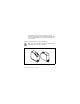
Wiring for High Vibration Applications If an application using the NI 9215 with screw terminal is subject to high vibration, National Instruments recommends that you either use ferrules to terminate wires to the detachable screw-terminal connector or use the NI 9932 backshell kit to protect the connections. Refer to Figure 7 for an illustration of using ferrules. Refer to Figure 1 for an illustration of the NI 9932 connector backshell. Figure 7.
NI 9215 Circuitry The NI 9215 channels share a common ground that is isolated from other modules in the system. The NI 9215 protects each channel from overvoltages. For more information about overvoltage protection, refer to the Specifications section. The incoming analog signal on each channel is buffered and conditioned by the instrumentation amplifier and is then sampled by a 16-bit ADC. The channels have independent track-and-hold amplifiers that allow you to sample all four channels simultaneously.
AI+ Overvoltage Protection + AI– Overvoltage Protection – COM Isolated ADC Instrumentation Amplifier NI 9215 with Screw Terminal Figure 8. Input Circuitry for One Channel on the NI 9215 with Screw Terminal NI 9215 Operating Instructions and Specifications 16 ni.
The NI 9215 with BNC has a resistor that ensures the input voltage does not drift outside of the common-mode range. AI+ Overvoltage Protection Overvoltage Protection AI– + Isolated ADC – Instrumentation Amplifier 100 kΩ NI 9215 with BNC Figure 9. Input Circuitry for One Channel on the NI 9215 with BNC © National Instruments Corp.
Sleep Mode This module supports a low-power sleep mode. Support for sleep mode at the system level depends on the chassis that the module is plugged into. Refer to the chassis manual for information about support for sleep mode. If the chassis supports sleep mode, refer to the software help for information about enabling sleep mode. Visit ni.com/info and enter cseriesdoc for information about C Series documentation. Typically, when a system is in sleep mode, you cannot communicate with the modules.
Specifications The following specifications are typical for the range –40 to 70 °C unless otherwise noted. Input Characteristics Number of channels.......................... 4 analog input channels ADC resolution................................. 16 bits Type of ADC..................................... Successive approximation register (SAR) Input range ........................................ ±10.0 V © National Instruments Corp.
Input voltage ranges1 Measurement Voltage, Maximum Voltage (Signal + Common Mode) AI+ to AI– Minimum* (V) Typical (V) Maximum (V) Screw Terminal BNC ±10.2 ±10.4 ±10.6 Each channel must remain within ±10.2 V of common. All inputs must remain within 10.2 V of the average AI– inputs. * The minimum measurement voltage range is the largest voltage the NI 9215 is guaranteed to accurately measure. 1 Refer to the Safety Guidelines section for more information about safe operating voltages.
Overvoltage protection ..................... ±30 V Conversion time Channel 0 only ........................... 4.4 μs Channels 0 and 1 ........................ 6 μs Channels 0, 1, and 2 ................... 8 μs Channels 0, 1, 2, and 3 ............... 10 μs Accuracy Percent of Reading (Gain Error) Percent of Range* (Offset Error) Calibrated, max (–40 to 70 °C) 0.2% 0.082% Calibrated, typ (25 °C, ±5 °C) 0.02% 0.014% Uncalibrated, max (–40 to 70 °C) 1.05% 0.82% Uncalibrated, typ (25 °C, ±5 °C) 0.
CMRR (fin = 60 Hz) .......................... –73 dB min Input bandwidth (–3 dB)................... 420 kHz min Input impedance Resistance NI 9215 with screw terminal ...................... 1 GΩ NI 9215 with BNC (Between any two AI– terminals) ...................... 200 kΩ Input bias current .............................. 10 nA Input noise RMS ........................................... 1.2 LSBrms Peak-to-peak............................... 7 LSB Crosstalk ...........................................
NI 9215 with BNC 10 V step .............................. 25 μs 20 V step .............................. 35 μs No missing codes.............................. 15 bits guaranteed DNL .................................................. –1.9 to 2 LSB max INL.................................................... ±6 LSB max MTBF ...............................................
Thermal dissipation (at 70 °C) Active mode ............................... 560 mW max Sleep mode ................................. 25 μW max Physical Characteristics If you need to clean the module, wipe it with a dry towel. Screw-terminal wiring ...................... 12 to 24 AWG copper conductor wire with 10 mm (0.39 in.) of insulation stripped from the end Torque for screw terminals ............... 0.5 to 0.6 N · m (4.4 to 5.3 lb · in.) Ferrules ............................................. 0.
Safety NI 9215 with Screw Terminal Safety Voltages Connect only voltages that are within the following limits. Channel-to-COM .............................. ±30 V max Isolation Channel-to-channel .................... No isolation between channels Channel-to-earth ground Continuous ........................... 250 Vrms, Measurement Category II Withstand .............................
Caution Do not connect the NI 9215 with screw terminal to signals or use for measurements within Measurement Categories III or IV. NI 9215 with BNC Safety Voltages Connect only voltages that are within the following limits. AI+-to-AI–........................................ ±30 V max Isolation Channel-to-channel .................... No isolation between channels Channel-to-earth ground Continuous ........................... 60 VDC, Measurement Category I Withstand .............................
equipment, limited-energy parts of equipment, circuits powered by regulated low-voltage sources, and electronics. Caution Do not connect the NI 9215 with BNC to signals or use for measurements within Measurement Categories II, III, or IV.
Hazardous Locations U.S. (UL) .......................................... Class I, Division 2, Groups A, B, C, D, T4; Class I, Zone 2, AEx nC IIC T4 Canada (C-UL) ................................. Class I, Division 2, Groups A, B, C, D, T4; Class I, Zone 2, Ex nC IIC T4 Europe (DEMKO)............................. EEx nC IIC T4 Environmental National Instruments C Series modules are intended for indoor use only but may be used outdoors if installed in a suitable enclosure.
Operating humidity (IEC 60068-2-56).............................. 10 to 90% RH, noncondensing Storage humidity (IEC 60068-2-56).............................. 5 to 95% RH, noncondensing Maximum altitude............................. 2,000 m Pollution Degree (IEC 60664) .......... 2 Shock and Vibration To meet these specifications, you must panel mount the system.
Electromagnetic Compatibility This product is designed to meet the requirements of the following standards of EMC for electrical equipment for measurement, control, and laboratory use: • EN 61326 EMC requirements; Industrial Immunity • EN 55011 Emissions; Group 1, Class A • CE, C-Tick, ICES, and FCC Part 15 Emissions; Class A Note For EMC compliance, operate this device with shielded cabling.
ni.com/certification, search by module number or product line, and click the appropriate link in the Certification column. Environmental Management National Instruments is committed to designing and manufacturing products in an environmentally responsible manner. NI recognizes that eliminating certain hazardous substances from our products is beneficial not only to the environment but also to NI customers. For additional environmental information, refer to the NI and the Environment Web page at ni.
⬉ᄤֵᙃѻક∵ᶧࠊㅵ⧚ࡲ⊩ ˄Ё RoHS˅ Ёᅶ᠋ National Instruments ヺড়Ё⬉ᄤֵᙃ ѻકЁ䰤ࠊՓ⫼ᶤѯ᳝ᆇ⠽䋼ᣛҸ (RoHS)DŽ݇Ѣ National Instruments Ё RoHS ড়㾘ᗻֵᙃˈ䇋ⱏᔩ ni.com/environment/rohs_chinaDŽ (For information about China RoHS compliance, go to ni.com/ environment/rohs_china.) Calibration You can obtain the calibration certificate and information about calibration services for the NI 9215 at ni.com/calibration. Calibration interval ...........................
National Instruments also has offices located around the world to help address your support needs. For telephone support in the United States, create your service request at ni.com/support and follow the calling instructions or dial 512 795 8248.
National Instruments, NI, ni.com, and LabVIEW are trademarks of National Instruments Corporation. Refer to the Terms of Use section on ni.com/legal for more information about National Instruments trademarks. Other product and company names mentioned herein are trademarks or trade names of their respective companies. For patents covering National Instruments products, refer to the appropriate location: Help»Patents in your software, the patents.txt file on your CD, or ni.com/patents.