Intelligent DAQ NI R Series Intelligent DAQ User Manual NI 781xR, 783xR, NI 784xR, and NI 785xR Devices R Series Intelligent DAQ User Manual June 2008 370489F-01
Support Worldwide Technical Support and Product Information ni.
Important Information Warranty The NI 7811R/7813R/7830R/7831R/7833R/7841R/7842R/7851R/7852R/7853R/7854R is warranted against defects in materials and workmanship for a period of one year from the date of shipment, as evidenced by receipts or other documentation. National Instruments will, at its option, repair or replace equipment that proves to be defective during the warranty period. This warranty includes parts and labor.
Compliance Compliance with FCC/Canada Radio Frequency Interference Regulations Determining FCC Class The Federal Communications Commission (FCC) has rules to protect wireless communications from interference. The FCC places digital electronics into two classes. These classes are known as Class A (for use in industrial-commercial locations only) or Class B (for use in residential or commercial locations). All National Instruments (NI) products are FCC Class A products.
Contents About This Manual Conventions ...................................................................................................................vii Related Documentation..................................................................................................viii Reconfigurable I/O Documentation ................................................................viii Additional Resources.......................................................................................
Contents Types of Signal Sources ................................................................................................ 2-8 Floating Signal Sources .................................................................................. 2-8 Ground-Referenced Signal Sources ................................................................ 2-8 Input Modes...................................................................................................................
About This Manual This manual describes the electrical and mechanical aspects of the National Instruments 781xR/783xR/784xR/785xR devices and contains information about programming and using the devices. Conventions The following conventions appear in this manual: <> Angle brackets that contain numbers separated by an ellipsis represent a range of values associated with a bit or signal name—for example, AO <3..0>.
About This Manual monospace Text in this font denotes text or characters that you should enter from the keyboard, sections of code, programming examples, and syntax examples. This font is also used for the proper names of disk drives, paths, directories, programs, subprograms, subroutines, device names, functions, operations, variables, filenames, and extensions. Multifunction R Series Multifunction R Series refers to the NI 783xR, NI 784xR, and NI 785xR, which provide both analog and digital I/O.
About This Manual information about using the FPGA Module to create VIs that run on the NI 78xxR device. – • © National Instruments Corporation LabVIEW FPGA Module Release and Upgrade Notes—Contains information about installing the LabVIEW FPGA Module, describes new features, and provides upgrade information. To access this document, refer to ni.com/manuals. In LabVIEW 8.
About This Manual Additional Resources The following documents contain information you might find helpful: • NI Developer Zone tutorial, Field Wiring and Noise Considerations for Analog Signals, at ni.com/zone • PICMG CompactPCI 2.0 R3.0 • PXI Hardware Specification Revision 2.1 • PXI Software Specification Revision 2.1 • National Instruments Example Finder—LabVIEW contains an extensive library of VIs and example programs for use with R Series devices.
1 Introduction This chapter describes the NI 781xR/783xR/784xR/785xR, the concept of the Reconfigurable I/O (RIO) device, optional software and equipment for using the NI 78xxR, and safety information about the NI 78xxR. About the Reconfigurable I/O Device Table 1-1 lists an overview of the NI 78xxR R Series Intelligent DAQ RIO devices. Table 1-1.
Chapter 1 Introduction instrument (VI) to the FPGA. Using the FPGA Module, you can graphically design the timing and functionality of the R Series device. If you only have LabVIEW but not the FPGA Module, you cannot create new FPGA VIs, but you can create VIs that run on Windows or a LabVIEW Real-Time (RT) target to control existing FPGA VIs. Some applications require tasks such as real-time, floating-point processing or datalogging while performing I/O and logic on the R Series device.
Chapter 1 Introduction PXI-specific features are implemented on the J2 connector of the CompactPCI bus. Table 1-2 lists the J2 pins used by the NI PXI-78xxR. The NI 78xxR is compatible with any CompactPCI chassis with a sub-bus that does not drive these lines. Even if the sub-bus is capable of driving these lines, the R Series device is still compatible as long as those pins on the sub-bus are disabled by default and are never enabled. Caution Damage can result if the J2 lines are driven by the sub-bus.
Chapter 1 Introduction Flexible Functionality Flexible functionality allows the NI 78xxR to match individual application requirements and to mimic the functionality of fixed I/O devices. For example, you can configure an R Series device in one application for three 32-bit quadrature encoders and then reconfigure the R Series device in another application for eight 16-bit event counters.
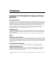
Chapter 1 Introduction Reconfigurable I/O Architecture Figure 1-1 shows an FPGA connected to fixed I/O resources and a bus interface. The fixed I/O resources include A/D converters (ADCs), D/A converters (DACs), and digital I/O lines. Fixed I/O Resource Fixed I/O Resource FPGA Fixed I/O Resource Fixed I/O Resource Bus Interface Figure 1-1.
Chapter 1 Introduction The FPGA does not retain the VI when the R Series device is powered off, so you must reload the VI each time you power on the device. You can load the VI from onboard flash memory or from software over the bus interface. One advantage to using flash memory is that the VI can start executing almost immediately after power up, instead of waiting for the computer to completely boot and load the FPGA VI.
Chapter 1 Introduction If you use the R Series device without the FPGA Module, you can use the RIO Device Setup utility, available by selecting Start»All Programs»National Instruments» NI-RIO»RIO Device Setup to download precomplied FPGA VIs to the flash memory of the R Series device. This utility installs with NI-RIO.
Chapter 1 Introduction Cables and Accessories National Instruments offers a variety of products you can use with R Series devices, including cables, connector blocks, and other accessories, as shown in Table 1-3. Table 1-3. R Series Connectivity Options Cable Connector Accessory 0 NI SCB-68 High-performance shielded cable wired specifically for signal connection from the RMIO connector† to the NI SCB-68 terminal block to provide higher signal integrity and noise immunity.
Chapter 1 Introduction Custom Cabling NI offers a variety of cables for connecting signals to the NI 78xxR. If you need to develop a custom cable, a nonterminated shielded cable is available from NI. The SHC68-NT-S connects to the NI 78xxR VHDCI connectors on one end of the cable. The other end of the cable is not terminated. This cable ships with a wire list identifying the wires that correspond to each NI 78xxR pin.
Chapter 1 Introduction • Pollution Degree 3 means that conductive pollution occurs, or dry, nonconductive pollution occurs that becomes conductive due to condensation. You must insulate signal connections for the maximum voltage for which the device is rated. Do not exceed the maximum ratings for the device. Do not install wiring while the device is live with electrical signals. Do not remove or add connector blocks when power is connected to the system.
Chapter 1 Introduction • Measurement Category III is for measurements performed in the building installation at the distribution level. This category refers to measurements on hard-wired equipment such as equipment in fixed installations, distribution boards, and circuit breakers. Other examples are wiring, including cables, bus bars, junction boxes, switches, socket outlets in the fixed installation, and stationary motors with permanent connections to fixed installations.
2 Hardware Overview of the NI 78xxR This chapter presents an overview of the hardware functions and I/O connectors on the NI 78xxR. Figure 2-1 shows a block diagram for the NI 781xR. Figure 2-2 shows a block diagram for the NI 7830R. Figure 2-3 shows a block diagram for the NI 7831R/7833R/784xR/785xR.
Hardware Overview of the NI 78xxR + – x4 Channels Input Mode Mux AISENSE AIGND Voltage Reference Calibration Mux 16-Bit DAC Configuration Control 16-Bit ADC Instrumentation Ampliflier AI– Connector 0 (MIO) Calibration DACs Input Mux UserConfigurable FPGA on RIO Devices Temperature Sensor 2 Calibration DACs Flash Memory Data/Address/ Control Bus Interface Control Address/Data x4 Channels PCI/PXI/CompactPCI Bus AI+ Configuration Chapter 2 Digital I/O (40) PXI Local Bus (NI PXI-7830R onl
Calibration DACs + Instrumentation Amplifier AI– 16-Bit ADC – Connector 0 (MIO) Configuration Control x8 Channels Flash Memory Configuration Input Mux AI+ Hardware Overview of the NI 78xxR Input Mode Mux AISENSE AIGND Voltage Reference Calibration Mux 16-Bit DAC UserConfigurable FPGA on RIO Devices Temperature Sensor 2 Calibration DACs Data/Address/ Control Bus Interface Control Address/Data x8 Channels PCI/PXI/CompactPCI Bus Chapter 2 Digital I/O (40) PXI Local Bus (NI PXI-783xR only
Chapter 2 Hardware Overview of the NI 78xxR NI 7831R/7833R Overview The NI 7831R/7833R each have eight independent, 16-bit AI channels; eight independent, 16-bit AO channels; 96 bidirectional DIO lines that you can configure individually for input or output; and a Virtex-II XC2V3000 FPGA. NI 784xR Overview The NI 784xR each have eight independent, 16-bit AI channels; eight independent, 16-bit AO channels; and 96 bidirectional DIO lines that you can configure individually for input or output.
Chapter 2 Hardware Overview of the NI 78xxR Table 2-1. Ideal Output Code and AI Voltage Mapping (Continued) Input Description AI Voltage Output Code (Hex) (Two’s Complement) Negative full-scale range +1 LSB –9.999695 8001 Negative full-scale range –10.000000 8000 Output Code ---------------------------------- × 10.0 V 32,768 — Any input voltage Input Modes The NI 783xR/784xR/785xR input mode is software configurable.
Chapter 2 Hardware Overview of the NI 78xxR Connecting Analog Input Signals The AI signals for the NI 783xR/784xR/785xR are AI<0..n>+, AI<0..n>–, AIGND, and AISENSE. For the NI 7830R, n=4. For the NI 7831R/7833R/784xR/785xR, n=8. The AI<0..n>+ and AI<0..n>– signals are connected to the eight AI channels of the NI 783xR/784xR/785xR. For all input modes, the AI<0..n>+ signals are connected to the positive input of the instrumentation amplifier on each channel.
Chapter 2 Hardware Overview of the NI 78xxR Connection of AI signals to the NI 783xR/784xR/785xR depends on the input mode of the AI channels you are using and the type of input signal source. With different input modes, you can use the instrumentation amplifier in different ways. Figure 2-4 shows a diagram of the NI 783xR/784xR/785xR instrumentation amplifier. Vin+ + Instrumentation Amplifier + Vm – – Vin– Measured Voltage Vm = [Vin+ – Vin–] Figure 2-4.
Chapter 2 Hardware Overview of the NI 78xxR Types of Signal Sources When configuring the input channels and making signal connections, you must first determine whether the signal sources are floating or ground referenced. The following sections describe these two signal types. Floating Signal Sources A floating signal source is not connected to the building ground system but instead has an isolated ground-reference point.
Chapter 2 Hardware Overview of the NI 78xxR Figure 2-5 summarizes the recommended input mode for both types of signal sources.
Chapter 2 Hardware Overview of the NI 78xxR Differential Connection Considerations (DIFF Input Mode) In DIFF input mode, the NI 783xR/784xR/785xR measures the difference between the positive and negative inputs. DIFF input mode is ideal for measuring ground-referenced signals from other devices. When using DIFF input mode, the input signal connects to the positive input of the instrumentation amplifier and its reference signal, or return, connects to the negative input of the instrumentation amplifier.
Chapter 2 Hardware Overview of the NI 78xxR Differential Connections for Ground-Referenced Signal Sources Figure 2-6 shows how to connect a ground-referenced signal source to a channel on the NI 783xR/784xR/785xR configured in DIFF input mode. AI+ GroundReferenced Signal Source + + AI– Instrumentation Amplifier Vs – – + Vm – CommonMode Noise and Ground Potential Measured Voltage + Vcm AISENSE – AIGND I/O Connector DIFF Input Mode Selected Figure 2-6.
Chapter 2 Hardware Overview of the NI 78xxR Differential Connections for Nonreferenced or Floating Signal Sources Figure 2-7 shows how to connect a floating signal source to a channel on the NI 783xR/784xR/785xR configured in DIFF input mode. Floating Signal Source + Vs Bias Resistors (see text) AI+ + AI– Instrumentation Amplifier – – + Vm – Measured Voltage Bias Current Return Paths AISENSE AIGND I/O Connector DIFF Input Mode Selected Figure 2-7.
Chapter 2 Hardware Overview of the NI 78xxR line to AIGND, connect it to AIGND through a resistor that is about 100 times the equivalent source impedance. The resistor puts the signal path nearly in balance. About the same amount of noise couples onto both connections, which yields better rejection of electrostatically coupled noise. Also, this input mode does not load down the source, other than the very high-input impedance of the instrumentation amplifier.
Chapter 2 Hardware Overview of the NI 78xxR Use DIFF input connections for greater signal integrity for any input signal that does not meet the preceding conditions. You can configure the NI 783xR/784xR/785xR channels in software for RSE or NRSE input modes. Use the RSE input mode for floating signal sources. In this case, the NI 783xR/784xR/785xR provides the reference ground point for the external signal. Use the NRSE input mode for ground-referenced signal sources.
Chapter 2 Hardware Overview of the NI 78xxR Single-Ended Connections for Grounded Signal Sources (NRSE Input Mode) To measure a grounded signal source with a single-ended input mode, you must configure the NI 783xR/784xR/785xR in the NRSE input mode. Then connect the signal to the positive input of the NI 783xR/784xR/785xR instrumentation amplifier and connect the signal local ground reference to the negative input of the instrumentation amplifier.
Chapter 2 Hardware Overview of the NI 78xxR Common-Mode Signal Rejection Considerations Figure 2-6 and Figure 2-9 show connections for signal sources that are already referenced to some ground point with respect to the NI 783xR/784xR/785xR. In these cases, the instrumentation amplifier can reject any voltage caused by ground potential differences between the signal source and the device.
Chapter 2 Hardware Overview of the NI 78xxR Connecting Analog Output Signals The AO signals are AO <0..n> and AOGND. AO <0..n> are the AO channels. AOGND is the ground reference signal for the AO channels. Figure 2-10 shows how to make AO connections to the NI 783xR/784xR/785xR. AO0 + Channel 0 Load VOUT 0 – AOGND0 NI 783xR/784xR/785xR Figure 2-10. Analog Output Connections Digital I/O You can configure the NI 78xxR DIO lines individually for either input or output.
Chapter 2 Hardware Overview of the NI 78xxR NI 7830R has one RMIO and one RDIO connector for a total of 56 DIO lines. The NI 7831R/7833R/784xR/785xR has one RMIO and two RDIO connectors for a total of 96 DIO lines. Refer to Figure A-1, NI 781xR Connector Pin Assignments and Locations, for the connector locations and the I/O connector pin assignments on the NI 781xR.
Chapter 2 Hardware Overview of the NI 78xxR LED DGND +5 V TTL or LVCMOS* Compatible Devices DIO<4..7> 5 V CMOS † TTL, LVTTL, CMOS, or LVCMOS Signal DIO<0..3> +5 V Switch DGND I/O Connector NI 783xR/784xR/785xR *3.3 V CMOS †Use a pull-up resistor when driving 5 V CMOS devices. Figure 2-11. Example Digital I/O Connections Figure 2-11 shows DIO<0..3> configured for digital input and DIO<4..7> configured for digital output.
Chapter 2 Hardware Overview of the NI 78xxR The SHC68-68-RDIO was designed specifically for R Series devices and is the NI-recommended cable for digital applications. If you are using the SH68-C68-S cable, however, please note the following considerations. The SH68-C68-S shielded cable contains 34 twisted pairs of conductors. To maximize the digital I/O available on the NI 78xxR, some of the DIO lines are twisted with power or ground and some DIO lines are twisted with other DIO lines.
Chapter 2 Hardware Overview of the NI 78xxR RTSI Trigger Bus The NI 78xxR can send and receive triggers through the RTSI trigger bus. The RTSI bus provides eight shared trigger lines that connect to all the devices on the bus. In PXI, the trigger lines are shared between all the PXI slots in a bus segment. In PCI, the RTSI bus is implemented through a ribbon cable connected to the RTSI connector on each device that needs to access the RTSI bus.
Chapter 2 Hardware Overview of the NI 78xxR The PXI local bus right lines on the NI PXI-781xR/783xR are PXI/LBR<0..12>. The PXI local bus left lines on the NI PXI-781xR/783xR are PXI/LBLSTAR<0..12>. The NI PXI-781xR/783xR can configure each PXI local bus line either as an input or an output signal. Only one device can drive the same physical local bus line at a time.
Chapter 2 Hardware Overview of the NI 78xxR LBLStar0 LBLStar1 LBLStar2 LBLStar3 LBR0 LBR1 LBR2 LBR3 Slot 2 LBLStar0 LBLStar1 LBLStar2 LBLStar3 PXI Star LBR0 LBR1 LBR2 LBR3 Trigger 0 Trigger 1 Trigger 2 Trigger 3 PXI Star Trigger 0 Trigger 1 Trigger 2 Trigger 3 PXI Star* Trigger 0 Trigger 1 Trigger 2 Trigger 3 2 LBLStar0 LBLStar1 LBLStar2 LBLStar3 Slot 3 LBR0 LBR1 LBR2 LBR3 Slot 4 3 1 * A Slot 2 device ties the PXI Star Line to the PXI 10 MHz clock 1 Shared Local Bus Lines between Slot 2 an
Chapter 2 Hardware Overview of the NI 78xxR SW1, SW2, SW3 Figure 2-13. Switch Location on the NI PCI-781xR R Series Intelligent DAQ User Manual 2-24 ni.
Chapter 2 Hardware Overview of the NI 78xxR SW1, SW2, SW3 NI PX Reconfi I-7811R gurable I/O CONNECTOR 3 (DIO) CONNECTOR 2 (DIO) Figure 2-14.
Chapter 2 Hardware Overview of the NI 78xxR SW1, SW2, SW3 Figure 2-15. Switch Location on the NI PCI-783xR R Series Intelligent DAQ User Manual 2-26 ni.
Chapter 2 Hardware Overview of the NI 78xxR SW1, SW2, SW3 Figure 2-16. Switch Location on the NI PXI-783xR ON ON 1 2 3 a. Normal Operation (Default) 1 2 3 b. Prevent VI From Loading Figure 2-17. Switch Settings Complete the following steps to prevent a VI stored in flash memory from loading to the FPGA: 1. Power off and unplug the PXI/CompactPCI chassis or PCI computer. 2. Remove the NI 781xR/783xR from the PXI/CompactPCI chassis or PCI computer.
Chapter 2 Hardware Overview of the NI 78xxR 3. Move SW1 to the ON position, as shown in Figure 2-17b. 4. Reinsert the NI 781xR/783xR into the PXI/CompactPCI chassis or PCI computer. Refer to the Installing the Hardware section of the Getting Started with R Series Intelligent DAQ document for installation instructions. 5. Plug in and power on the PXI/CompactPCI chassis or PCI computer. After completing this procedure, a VI stored in flash memory does not load to the FPGA at power-on.
Chapter 2 Hardware Overview of the NI 78xxR (NI 784xR/785xR Devices) All NI 784xR/785xR devices have a user-replaceable socketed fuse to protect the supply from overcurrent conditions. When an overcurrent condition occurs, check your cabling to the +5 V terminals and replace the fuse as described in the Device Fuse Replacement (NI 784xR/785xR Only) section. Never connect the +5 V power terminals to analog or digital ground or to any other voltage source on the NI 78xxR device or any other device.
Chapter 2 Hardware Overview of the NI 78xxR 3. Replace the broken fuse while referring to Figure 2-18 for the fuse locations. 1 1 Littelfuse Part Number 0453 004 (NI Part Number 766247-01) Figure 2-18. NI 784xR/785xR Replacement Fuse Location 4. R Series Intelligent DAQ User Manual Reinstall the PCI or PXI device into the computer or PXI chassis. 2-30 ni.
Chapter 2 Hardware Overview of the NI 78xxR Field Wiring Considerations (NI 783xR/784xR/785xR Only) Environmental noise can seriously affect the measurement accuracy of the device if you do not take proper care when running signal wires between signal sources and the device. The following recommendations mainly apply to AI signal routing to the device, as well as signal routing in general.
Calibration (NI 783xR/784xR/785xR Only) 3 Calibration is the process of determining and/or adjusting the accuracy of an instrument to minimize measurement and output voltage errors. On the NI 783xR/784xR/785xR, onboard calibration DACs (CalDACs) correct these errors. Because the analog circuitry handles calibration, the data read from the AI channels or written to the AO channels in the FPGA VI is already calibrated.
Chapter 3 Calibration (NI 783xR/784xR/785xR Only) application. Internal calibration minimizes the effects of any offset and gain drifts, particularly those due to changes in temperature. During the internal calibration process, the AI and AO channels are compared to the NI 783xR/784xR/785xR onboard voltage reference. The offset and gain errors in the analog circuitry are calibrated out by adjusting the CalDACs to minimize these errors.
Chapter 3 Calibration (NI 783xR/784xR/785xR Only) To externally calibrate your device, use an external reference several times more accurate than the device itself. For more information on externally calibrating your NI 783xR/784xR/785xR device, refer to the NI 783xR Calibration Procedure for NI-RIO, found on ni.com/manuals.
Connecting I/O Signals A This appendix describes how to make input and output signal connections to the NI 78xxR I/O connectors. Figure A-1 shows the I/O connector pin assignments and locations for NI PCI-7811R/7813R and NI PXI-7811R/7813R. Figure A-2 shows the I/O connector pin assignments and locations for NI PCI-7830R/7831R/7833R and the NI PXI-7830R/7831R/7833R/ 7841R/7842R/7851R/7852R/7853R/7854R. Note The NI PXI-7830R and NI PCI-7830R do not have Connector 2 (RDIO).
DIO35 DIO33 DIO31 DIO29 DIO27 DIO26 DIO25 DIO24 DIO23 DIO22 DIO21 DIO20 DIO19 DIO18 DIO17 DIO16 DIO15 DIO14 DIO13 DIO12 DIO11 DIO10 DIO9 DIO8 DIO7 DIO6 DIO5 DIO4 DIO3 DIO2 DIO1 34 33 32 31 30 29 28 27 26 25 24 23 22 21 20 19 18 17 16 15 14 13 12 11 10 9 8 7 6 5 4 3 2 1 DIO38 DIO36 DIO34 DIO32 DIO30 DIO28 +5V TERMINAL 68 TERMINAL 35 TERMINAL 34 TERMINAL 1 DGND TERMINAL 1 TERMINAL 34 DGND DGND DGND TERMINAL 35 TERMINAL 68 TERMINAL 68 TERMINAL 35 TERMINAL 34 TERMINAL 1 TERMINAL 1 TERMINAL 34
Connecting I/O Signals CONNECTOR 0 (RMIO) Appendix A DIO35 DIO33 DIO31 DIO29 DIO27 DIO26 DIO25 DIO24 DIO23 DIO22 DIO21 DIO20 DIO19 DIO18 DIO17 DIO16 DIO15 DIO14 DIO13 DIO12 DIO11 DIO10 DIO9 DIO8 DIO7 DIO6 DIO5 DIO4 DIO3 DIO2 DIO1 34 33 32 31 30 29 28 27 26 25 24 23 22 21 20 19 18 17 16 15 14 13 12 11 10 9 8 7 6 5 4 3 2 1 DIO38 DIO36 DIO34 DIO32 DIO30 DIO28 +5V AI0+ AIGND0 AI1+ AI2+ AIGND2 AI3+ AI4+1 TERMINAL 68 TERMINAL 34 +5V DGND DGND AIGND4 AI5+1 AI6+1 DGND DGND TERMINAL 1 AIGND6 AI7+1 DGND
Appendix A Connecting I/O Signals To access the signals on the I/O connectors, you must connect a cable from the I/O connector to a signal accessory. Plug the small VHDCI connector end of the cable into the appropriate I/O connector and connect the other end of the cable to the appropriate signal accessory. Table A-1. I/O Connector Signal Descriptions Signal Name Reference Direction Description DGND Output +5 VDC Source—These pins supply 5 V from the computer power supply.
Appendix A Connecting I/O Signals Connections that exceed any of the maximum ratings of input or output signals on the NI 78xxR can damage the NI 78xxR and the computer. Maximum input ratings for each signal are in the Protection column of Table A-2. NI is not liable for any damage resulting from such signal connections Caution Table A-2.
Appendix A Connecting I/O Signals Connecting to 5B and SSR Analog Signal Conditioning (NI 783xR/784xR/785xR Only) NI provides cables that allow you to connect signals from the NI 783xR/784xR/785xR directly to 5B backplanes for analog signal conditioning and SSR backplanes for digital signal conditioning. The NSC68-262650 cable connects the signals on the NI 783xR/784xR/785xR RMIO connector directly to 5B and SSR backplanes.
Appendix A Connecting I/O Signals Figure A-3 shows the connector pinouts when using the NSC68-262650 cable.
Appendix A Connecting I/O Signals You can plug each of these 50-pin headers directly into an 8-, 16-, 24-, or 32-channel SSR backplane for digital signal conditioning. One of the 50-pin headers contains DIO<0..23> from the NI 78xxR RDIO connector. These lines correspond to Slots <0..23> on an SSR backplane in sequential order. The other 50-pin header contains DIO<24..39> from the NI 78xxR RDIO connector. These lines correspond to Slots <0..15> on an SSR backplane in sequential order.
B Using the SCB-68 Shielded Connector Block This appendix describes how to connect input and output signals to the NI 78xxR with the SCB-68 shielded connector block. The SCB-68 has 68 screw terminals for I/O signal connections. To use the SCB-68 with the NI 78xxR, you must configure the SCB-68 as a general-purpose connector block. Refer to Figure B-1 for the general-purpose switch configuration. S1 S2 S5 S4 S3 Figure B-1.
Technical Support and Professional Services C Visit the following sections of the award-winning National Instruments Web site at ni.com for technical support and professional services: • Support—Technical support resources at ni.com/support include the following: – Self-Help Technical Resources—For answers and solutions, visit ni.
Appendix C Technical Support and Professional Services • Declaration of Conformity (DoC)—A DoC is our claim of compliance with the Council of the European Communities using the manufacturer’s declaration of conformity. This system affords the user protection for electromagnetic compatibility (EMC) and product safety. You can obtain the DoC for your product by visiting ni.com/certification.
Glossary Symbol Prefix Value p pico 10 –12 n nano 10 –9 µ micro 10 – 6 m milli 10 –3 k kilo 10 3 M mega 10 6 G giga 10 9 Numbers/Symbols ° Degrees. > Greater than. ≥ Greater than or equal to. < Less than. ≤ Less than or equal to. – Negative of, or minus. Ω Ohms. / Per. % Percent. ± Plus or minus. + Positive of, or plus.
Glossary Square root of. +5V +5 VDC source signal. A A Amperes. A/D Analog-to-digital. AC Alternating current. ADC Analog-to-digital converter—An electronic device, often an integrated circuit, that converts an analog voltage to a digital number. AI Analog input. AI Analog input channel signal. AIGND Analog input ground signal. AISENSE Analog input sense signal. AO Analog output. AO Analog output channel signal. AOGND Analog output ground signal.
Glossary C C Celsius. CalDAC Calibration DAC. CH Channel—Pin or wire lead to which you apply or from which you read the analog or digital signal. Analog signals can be single-ended or differential. For digital signals, you group channels to form ports. Ports usually consist of either four or eight digital channels. cm Centimeter. CMOS Complementary metal-oxide semiconductor.
Glossary DIO Digital input/output. DIO Digital input/output channel signal. DMA Direct memory access—A method by which data can be transferred to/from computer memory from/to a device or memory on the bus while the processor does something else. DMA is the fastest method of transferring data to/from computer memory. DNL Differential nonlinearity—A measure in LSB of the worst-case deviation of code widths from their ideal value of 1 LSB. DO Digital output.
Glossary I I/O Input/output—The transfer of data to/from a computer system involving communications channels, operator interface devices, and/or data acquisition and control interfaces. INL Relative accuracy. L LabVIEW Laboratory Virtual Instrument Engineering Workbench. LabVIEW is a graphical programming language that uses icons instead of lines of text to create programs. LSB Least significant bit. M m Meter. max Maximum. MIMO Multiple input, multiple output. min Minimum.
Glossary N noise An undesirable electrical signal—Noise comes from external sources such as the AC power line, motors, generators, transformers, fluorescent lights, CRT displays, computers, electrical storms, welders, radio transmitters, and internal sources such as semiconductors, resistors, and capacitors. Noise corrupts signals you are trying to send or receive.
Glossary R RAM Random-access memory—The generic term for the read/write memory that is used in computers. RAM allows bits and bytes to be written to it as well as read from. Various types of RAM are DRAM, EDO RAM, SRAM, and VRAM. resolution The smallest signal increment that can be detected by a measurement system. Resolution can be expressed in bits, in proportions, or in percent of full scale. For example, a system has 12-bit resolution, one part in 4,096 resolution, and 0.0244% of full scale.
Glossary T THD Total harmonic distortion—The ratio of the total rms signal due to harmonic distortion to the overall rms signal, in decibel or a percentage. thermocouple A temperature sensor created by joining two dissimilar metals. The junction produces a small voltage as a function of the temperature. TTL Transistor-transistor logic. two’s complement Given a number x expressed in base 2 with n digits to the left of the radix point, the (base 2) number 2n – x. V V Volts.