Reconfigurable I/O NI 783xR User Manual Reconfigurable I/O Devices for PCI/PXI/CompactPCI Bus Computers NI 783xR User Manual May 2005 370489C-01
Support Worldwide Technical Support and Product Information ni.
Important Information Warranty The NI 7830R/7831R/7833R is warranted against defects in materials and workmanship for a period of one year from the date of shipment, as evidenced by receipts or other documentation. National Instruments will, at its option, repair or replace equipment that proves to be defective during the warranty period. This warranty includes parts and labor.
Compliance Compliance with FCC/Canada Radio Frequency Interference Regulations Determining FCC Class The Federal Communications Commission (FCC) has rules to protect wireless communications from interference. The FCC places digital electronics into two classes. These classes are known as Class A (for use in industrial-commercial locations only) or Class B (for use in residential or commercial locations). All National Instruments (NI) products are FCC Class A products.
Contents About This Manual Conventions ...................................................................................................................vii Reconfigurable I/O Documentation...............................................................................viii Related Documentation..................................................................................................ix Chapter 1 Introduction About the NI 783xR..........................................................................
Contents Input Modes................................................................................................................... 2-6 Differential Connection Considerations (DIFF Input Mode) ......................... 2-8 Differential Connections for Ground-Referenced Signal Sources ... 2-8 Differential Connections for Nonreferenced or Floating Signal Sources ................................................................. 2-9 Single-Ended Connection Considerations ...................................
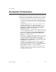
About This Manual This manual describes the electrical and mechanical aspects of the National Instruments 783xR devices and contains information about programming and using the devices. Conventions The following conventions appear in this manual: <> Angle brackets that contain numbers separated by an ellipsis represent a range of values associated with a bit or signal name—for example, DIO<3..0>. » The » symbol leads you through nested menu items and dialog box options to a final action.
About This Manual Reconfigurable I/O Documentation The NI 783xR User Manual is one piece of the documentation set for your reconfigurable I/O system and application. Depending on the hardware and software you use for your application, you could have any of several types of documentation.
About This Manual Related Documentation The following documents contain information you might find helpful: • NI Developer Zone tutorial, Field Wiring and Noise Considerations for Analog Signals, at ni.com/zone • PICMG CompactPCI 2.0 R3.0 • PXI Hardware Specification Revision 2.1 • PXI Software Specification Revision 2.
1 Introduction This chapter describes the NI 783xR, the concept of the Reconfigurable I/O (RIO) device, optional software and equipment for using the NI 783xR, and safety information about the NI 783xR. About the NI 783xR The NI 783xR devices are R Series RIO devices with 16-bit analog input (AI) channels, 16-bit analog output (AO) channels, and digital I/O (DIO) lines. • The NI PXI-7830R and NI PCI-7830R have four independent AI channels, four independent AO channels, and 56 DIO lines.
Chapter 1 Introduction The NI 783xR uses the Real-Time System Integration (RTSI) bus to easily synchronize several measurement functions to a common trigger or timing event. The NI PCI-783xR accesses the RTSI bus through a RTSI cable connected between devices. The NI PXI-783xR accesses the RTSI bus through the PXI trigger lines implemented on the PXI backplane. Refer to Appendix A, Specifications, for detailed NI 783xR specifications.
Chapter 1 Introduction Table 1-1. Pins Used by the NI PXI-783xR NI PXI-783xR Signal PXI Pin Name PXI J2 Pin Number PXI Trigger<0..7> PXI Trigger<0..7> A16, A17, A18, B16, B18, C18, E16, E18 PXI Clock 10 MHz PXI Clock 10 MHz E17 PXI Star Trigger PXI Star Trigger D17 LBLSTAR<0..12> LBL<0..12> A1, A19, C1, C19, C20, D1, D2, D15, D19, E1, E2, E19, E20 LBR<0..12> LBR<0..
Chapter 1 Introduction User-Defined I/O Resources You can create your own custom measurements using the fixed I/O resources. For example, one application might require an event counter that increments when a rising edge appears on any of three digital input lines. Another application might require a digital line to be asserted after an analog input exceeds a programmable threshold. Device-Embedded Logic and Processing You can implement LabVIEW logic and processing in the FPGA of the R Series device.
Chapter 1 Introduction The FPGA logic provides timing, triggering, processing, and custom I/O measurements. Each fixed I/O resource used by the application uses a small portion of the FPGA logic that controls the fixed I/O resource. The bus interface also uses a small portion of the FPGA logic to provide software access to the device. The remaining FPGA logic is available for higher-level functions such as timing, triggering, and counting. The functions use varied amounts of logic.
Chapter 1 Introduction FPGA Interface User Guide, for information about the FPGA Interface functions. You can use Interactive Front Panel Communication to communicate directly with the VI running on the FPGA. You can use Programmatic FPGA Interface Communication to programmatically control and communicate with FPGA VIs from host VIs.
Chapter 1 Introduction Cables and Optional Equipment National Instruments offers a variety of products you can use with R Series devices, including cables, connector blocks, and other accessories, as shown in Table 1-2. Table 1-2. Cables and Accessories Cable SH68-C68-S NI 783xR Connector Cable Description Shielded 68-pin VHDCI male connector to female 0.050 series D-type connector. The cable is constructed with 34 twisted wire pairs and an overall shield.
Chapter 1 Introduction Table 1-2. Cables and Accessories (Continued) Cable NSC68-262650 NI 783xR Connector Cable Description Non-shielded cable connects from 68-pin VHDCI male connector to two 26-pin female headers plus one 50-pin female header. The pinout of these headers allows for direct connection to 5B backplanes for analog signal conditioning and SSR backplanes for digital signal conditioning.
Chapter 1 Introduction signals that you need to the connector of your choice. Refer to Appendix B, Connecting I/O Signals, for the NI 783xR connector pinouts. Safety Information The following section contains important safety information that you must follow when installing and using the NI 783xR. Do not operate the NI 783xR in a manner not specified in this document. Misuse of the NI 783xR can result in a hazard.
Chapter 1 Introduction to the system. Remove power from signal lines before connecting them to or disconnecting them from the NI 783xR. Operate the NI 783xR at or below the measurement category1 listed in the section Maximum working voltage, in Appendix A, Specifications. Measurement circuits are subjected to working voltages2 and transient stresses (overvoltage) from the circuit to which they are connected during measurement or test.
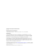
2 Hardware Overview of the NI 783xR This chapter presents an overview of the hardware functions and I/O connectors on the NI 783xR. Figure 2-1 shows a block diagram for the NI 7830R. Figure 2-2 shows a block diagram for the NI 7831R/7833R.
Hardware Overview of the NI 783xR + Instrumentation Amplifier AI– 16-Bit ADC – Connector 0 (MIO) Configuration Control x8 Channels Flash Memory Input Mode Mux AISENSE AIGND Voltage Reference Calibration Mux 16-Bit DAC UserConfigurable FPGA on RIO Devices Temperature Sensor 2 Calibration DACs Data/Address/ Control Control Bus Interface Address/Data x8 Channels PCI/PXI/CompactPCI Bus Calibration DACs Input Mux AI+ Configuration Chapter 2 Digital I/O (40) PXI Local Bus (NI PXI-783xR onl
Chapter 2 Hardware Overview of the NI 783xR ±10 V. The converters return data in two’s complement format. Table 2-1 shows the ideal output code returned for a given AI voltage. Table 2-1. Ideal Output Code and AI Voltage Mapping AI Voltage Output Code (Hex) (Two’s Complement) Full-scale range –1 LSB 9.999695 7FFF Full-scale range –2 LSB 9.999390 7FFE Midscale 0.000000 0000 Negative full-scale range +1 LSB –9.999695 8001 Negative full-scale range –10.
Chapter 2 Hardware Overview of the NI 783xR Input Range The NI 783xR AI range is fixed at ±10 V. Connecting Analog Input Signals The AI signals for the NI 783xR are AI<0..n>+, AI<0..n>–, AIGND, and AISENSE. For the NI 7830R, n=4. For the NI 7831R/7833R, n=8. The AI<0..n>+ and AI<0..n>– signals are connected to the eight AI channels of the NI 783xR. For all input modes, the AI<0..n>+ signals are connected to the positive input of the instrumentation amplifier on each channel.
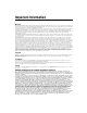
Chapter 2 Vin+ Hardware Overview of the NI 783xR + Instrumentation Amplifier + Vm – – Vin– Measured Voltage Vm = [Vin+ – Vin–] Figure 2-3. NI 783xR Instrumentation Amplifier The instrumentation amplifier applies common-mode voltage rejection and presents high input impedance to the AI signals connected to the NI 783xR. Input multiplexers on the device route signals to the positive and negative inputs of the instrumentation amplifier.
Chapter 2 Hardware Overview of the NI 783xR Types of Signal Sources When configuring the input channels and making signal connections, you must first determine whether the signal sources are floating or ground referenced. The following sections describe these two signal types. Floating Signal Sources A floating signal source is not connected to the building ground system but instead has an isolated ground-reference point.
Chapter 2 Hardware Overview of the NI 783xR Signal Source Type Floating Signal Source (Not Connected to Building Ground) Grounded Signal Source Examples • Ungrounded Thermocouples • Signal Conditioning with Isolated Outputs • Battery Devices Examples • Plug-in Instruments with Nonisolated Outputs Input AI(+) + V 1 – AI(–) + – AI(+) + V 1 – + AI(–) – Differential (DIFF) AIGND AIGND See text for information on bias resistors.
Chapter 2 Hardware Overview of the NI 783xR Differential Connection Considerations (DIFF Input Mode) In DIFF input mode, the NI 783xR measures the difference between the positive and negative inputs. DIFF input mode is ideal for measuring ground-referenced signals from other devices. When using DIFF input mode, the input signal connects to the positive input of the instrumentation amplifier and its reference signal, or return, connects to the negative input of the instrumentation amplifier.
Chapter 2 GroundReferenced Signal Source + Hardware Overview of the NI 783xR AI+ + AI– Instrumentation Amplifier Vs – – + Vm – CommonMode Noise and Ground Potential Measured Voltage + Vcm AISENSE – AIGND I/O Connector DIFF Input Mode Selected Figure 2-5.
Chapter 2 Floating Signal Source Hardware Overview of the NI 783xR + Vs Bias Resistors (see text) AI+ + AI– Instrumentation Amplifier – – + Vm – Measured Voltage Bias Current Return Paths AISENSE AIGND I/O Connector DIFF Input Mode Selected Figure 2-6. Differential Input Connections for Nonreferenced Signals Figure 2-6 shows two bias resistors connected in parallel with the signal leads of a floating signal source.
Chapter 2 Hardware Overview of the NI 783xR You can fully balance the signal path by connecting another resistor of the same value between the positive input and AIGND, as shown in Figure 2-6. This fully balanced input mode offers slightly better noise rejection but has the disadvantage of loading down the source with the series combination (sum) of the two resistors.
Chapter 2 Hardware Overview of the NI 783xR In single-ended input modes, electrostatic and magnetic noise couples into the signal connections more than in differential input modes. The coupling is the result of differences in the signal path. Magnetic coupling is proportional to the area between the two signal conductors. Electrical coupling is a function of how much the electric field differs between the two conductors.
Chapter 2 Hardware Overview of the NI 783xR positive and negative inputs of the instrumentation amplifier. The instrumentation amplifier rejects this difference. If the input circuitry of a NI 783xR is referenced to ground in RSE input mode, this difference in ground potentials appears as an error in the measured voltage. Figure 2-8 shows how to connect a grounded signal source to a channel on the NI 783xR configured for NRSE input mode.
Chapter 2 Hardware Overview of the NI 783xR Analog Output The bipolar output range of the NI 783xR AO channels is fixed at ±10 V. Some applications require that the AO channels power on to known voltage levels. To set the power-on levels, you can configure the NI 783xR to load and run a VI when the system powers on. The VI can set the AO channels to the desired voltage levels. The VI interprets data written to the DAC in two’s complement format.
Chapter 2 AO0 Hardware Overview of the NI 783xR Channel 0 + Load VOUT 0 – AOGND0 NI 783xR Figure 2-9. Analog Output Connections Digital I/O You can configure the NI 783xR DIO lines individually for either input or output. When the system powers on, the DIO lines are high impedance. To set another power-on state, you can configure the NI 783xR to load a VI when the system powers on. The VI can then set the DIO lines to any power-on state.
Chapter 2 Hardware Overview of the NI 783xR (3.3 V TTL), the DIO lines cannot drive 5 V CMOS logic levels. To interface to 5 V CMOS devices, you must provide an external pull-up resistor to 5 V. This resistor pulls up the 3.3 V digital output from the NI 783xR to 5 V CMOS logic levels. Refer to Appendix A, Specifications, for detailed DIO specifications. Exceeding the maximum input voltage ratings, listed in Table B-2, NI 783xR I/O Signal Summary, can damage the NI 783xR and the computer.
Chapter 2 Hardware Overview of the NI 783xR LED DGND +5 V TTL or LVCMOS* Compatible Devices DIO<4..7> 5 V CMOS† TTL, LVTTL, CMOS, or LVCMOS Signal DIO<0..3> +5 V Switch DGND I/O Connector NI 783xR *3.3 V CMOS †Use a pull-up resistor when driving 5 V CMOS devices. Figure 2-10. Example Digital I/O Connections Figure 2-10 shows DIO<0..3> configured for digital input and DIO<4..7> configured for digital output.
Chapter 2 Hardware Overview of the NI 783xR signals or non-edge-sensitive, low-frequency digital signals. Examples of high-frequency or edge-sensitive signals include clock, trigger, pulse-width modulation (PWM), encoder, and counter signals. Examples of static signals or non-edge-sensitive, low-frequency signals include LEDs, switches, and relays. Table 2-4 summarizes these guidelines. Table 2-4.
Chapter 2 Hardware Overview of the NI 783xR Do not drive the same RTSI trigger bus line with the NI 783xR and another device simultaneously. Such signal driving can damage both devices. NI is not liable for any damage resulting from such signal driving. Caution For more information on using and configuring triggers, select Help»VI, Function, & How-To Help in LabVIEW to view the LabVIEW Help. Refer to the PXI Hardware Specification Revision 2.1 and PXI Software Specification Revision 2.1 at www.pxisa.
Chapter 2 Hardware Overview of the NI 783xR delay-matched trigger signal between the first peripheral slot and the other peripheral slots for precise trigger timing signals. For example, an NI PXI-783xR in Slot 2 can send an independent trigger signal to each device plugged into Slots <3..15> using the PXI/LBLSTAR<0..12>. Each device receives its trigger signal on its own dedicated star trigger line.
Chapter 2 Hardware Overview of the NI 783xR SW1, SW2, SW3 Figure 2-11.
Chapter 2 Hardware Overview of the NI 783xR SW1, SW2, SW3 Figure 2-12. Switch Location on the NI PCI-783xR ON ON 1 2 3 a. Normal Operation (Default) 1 2 3 b. Prevent VI From Loading Figure 2-13. Switch Settings Complete the following steps to prevent a VI stored in Flash memory from loading to the FPGA: NI 783xR User Manual 1. Power off and unplug the PXI/CompactPCI chassis or PCI computer. 2. Remove the NI 783xR from the PXI/CompactPCI chassis or PCI computer. 3.
Chapter 2 Hardware Overview of the NI 783xR 4. Reinsert the NI 783xR into the PXI/CompactPCI chassis or PCI computer. Refer to the Installing the Hardware section of the Getting Started with the NI 783xR document for installation instructions. 5. Plug in and power on the PXI/CompactPCI chassis or PCI computer. After completing this procedure, a VI stored in Flash memory does not load to the FPGA at power-on. You can use software to configure the NI 783xR if necessary.
Chapter 2 Hardware Overview of the NI 783xR Field Wiring Considerations Environmental noise can seriously affect the measurement accuracy of the device if you do not take proper care when running signal wires between signal sources and the device. The following recommendations mainly apply to AI signal routing to the device. They also apply to signal routing in general.
3 Calibration Calibration is the process of determining and/or adjusting the accuracy of an instrument to minimize measurement and output voltage errors. On the NI 783xR, onboard calibration DACs (CalDACs) correct these errors. Because the analog circuitry handles calibration, the data read from the AI channels or written to the AO channels in the FPGA VI is already calibrated. Three levels of calibration are available for the NI 783xR to ensure the accuracy of its analog circuitry.
Chapter 3 Calibration If you have NI-RIO installed, you can find the internal calibration utility at Start»All Programs»National Instruments»NI-RIO»device»Calibrate 783xR Device. Device is the NI PXI-783xR or NI PCI-783xR device. Immediately after internal calibration, the only significant residual calibration error is gain error due to time and temperature drift of the onboard voltage reference. You can minimize gain errors by performing an external calibration.
A Specifications This appendix lists the specifications of the NI 783xR. These specifications are typical at 25 °C unless otherwise noted. Analog Input Input Characteristics Number of channels NI 7830R......................................... 4 NI 7831R......................................... 8 NI 7833R......................................... 8 Input modes............................................ DIFF, RSE, NRSE (software-selectable; selection applies to all channels) Type of ADC....................
Appendix A Specifications Maximum working voltage (signal + common mode) ........................Inputs should remain within ±12 V of ground Overvoltage protection ...........................±42 V Data transfers ..........................................Interrupts, programmed I/O Accuracy Information Relative Accuracy Absolute Accuracy Nominal Range (V) Noise + Quantization (µV) % of Reading Positive Full Scale Negative Full Scale 24 Hours 10.0 –10.0 0.
Appendix A Specifications Settling Time Accuracy Step Size 16 LSB 4 LSB 2 LSB ±20.0 V 7.5 µs 10.3 µs 40 µs ±2.0 V 2.7 µs 4.1 µs 5.1 µs ±0.2 V 1.7 µs 2.9 µs 3.6 µs Crosstalk................................................. –80 dB, DC to 100 kHz Analog Output Output Characteristics Output type............................................. Single-ended, voltage output Number of channels NI 7830R......................................... 4 NI 7831R.........................................
Appendix A Specifications Accuracy Information Absolute Accuracy Positive Full Scale Negative Full Scale 24 Hours 1 Year Offset (µV) Temp Drift (%/°C) Absolute Accuracy at Full Scale (mV) 10.0 –10.0 0.0335 0.0351 2366 0.0005 5.88 Nominal Range (V) % of Reading Note: Accuracies are valid for analog output following an internal calibration.
Appendix A Specifications Slew rate................................................. 10 V/µs Noise ...................................................... 150 µVrms, DC to 1 MHz Glitch energy at midscale transition ............................. ±200 mV for 3 µs Digital I/O Number of channels NI 7830R......................................... 56 NI 7831R......................................... 96 NI 7833R......................................... 96 Compatibility .........................................
Appendix A Specifications Reconfigurable FPGA Number of logic slices NI 7830R .........................................5,120 NI 7831R .........................................5,120 NI 7833R .........................................14,336 Equivalent number of logic cells NI 7830R .........................................11,520 NI 7831R .........................................11,520 NI 7833R .........................................32,256 Available embedded RAM NI 7830R ....................................
Appendix A Specifications Onboard calibration reference DC level .......................................... 5.000 V (±3.5 mV) (actual value stored in Flash memory) Temperature coefficient .................. ±5 ppm/°C max Long-term stability ......................... ±20 ppm/ 1,000 h Refer to Calibration Certificates at ni.com/calibration to generate a calibration certificate for the NI 783xR. Note Bus Interface PXI (NI PXI-783xR only) ...................... Master, slave PCI (NI PCI-783xR only) ........
Appendix A Specifications Physical Dimensions (not including connectors) NI PXI-783xR..................................16 cm by 10 cm (6.3 in. by 3.9 in.) NI PCI-783xR..................................17 cm by 11 cm (6.7 in. by 4.3 in.) I/O connectors.........................................Three 68-pin female high-density VHDCI type Maximum Working Voltage Maximum working voltage refers to the signal voltage plus the common-mode voltage. Channel-to-earth .....................................
Appendix A Specifications Relative humidity range ......................... 10% to 90%, noncondensing, tested in accordance with IEC-60068-2-56 Altitude................................................... 2,000 m at 25 °C ambient temperature Storage Environment Ambient temperature range.................... –20 °C to 70 °C tested in accordance with IEC-60068-2-1 and IEC-60068-2-2 Relative humidity range .........................
Appendix A Specifications Safety The NI 783xR is designed to meet the requirements of the following standards of safety for electrical equipment for measurement, control, and laboratory use: • IEC 61010-1, EN 61010-1 • UL 61010-1 • CAN/CSA-C22.2 No. 61010-1 Refer to the product label, or visit ni.com/certification, search by model number or product line, and click the appropriate link in the Certification column for UL and other safety certifications. Note Electromagnetic Compatibility Emissions..
B Connecting I/O Signals This appendix describes how to make input and output signal connections to the NI 783xR I/O connectors. Figure B-1 shows the I/O connector locations for the NI PXI-7831R/7833R and the NI PCI-7831R/7833R. The NI PXI-7830R and NI PCI-7830R do not have Connector 2 (DIO). CONNECTOR 0 (MIO) CONNECTOR 0 (MIO) CONNECTOR 2 (DIO) CONNECTOR 1 (DIO) CONNECTOR 2 (DIO) CONNECTOR 1 (DIO) Figure B-1.
Appendix B Connecting I/O Signals Figure B-2 shows the I/O connector pin assignments for the I/O connectors on the NI 783xR. The DIO connector pin assignment applies to connector 1 on the NI 7830R and connectors <1..2> on the NI 7831R/7833R.
Appendix B Connecting I/O Signals . Table B-1. I/O Connector Signal Descriptions Signal Name Reference Direction Description +5V DGND Output +5 VDC Source—These pins supply 5 V from the computer power supply using a self-resetting 1 A fuse. No more than 250 mA should be pulled from a single pin. AI<0..7>+ AIGND Input Positive input for Analog Input channels 0 through 7. AI<0..7>– AIGND Input Negative input for Analog Input channels 0 through 7.
Appendix B Connecting I/O Signals Table B-2. NI 783xR I/O Signal Summary Signal Type and Direction Impedance Input/ Output Protection (Volts) On/Off Source (mA at V) Sink (mA at V) Rise Time Bias +5V DO — — — — — — AI<0..7>+ AI 10 GΩ in parallel with 100 pF 42/35 — — — ±2 nA AI<0..7>– AI 10 GΩ in parallel with 100 pF 42/35 — — — ±2 nA AIGND AO — — — — — — AISENSE AI 10 GΩ in parallel with 100 pF 42/35 — — — ±2 nA AO<0..7> AO 1.
Appendix B Connecting I/O Signals Connecting to 5B and SSR Signal Conditioning NI provides cables that allow you to connect signals from the NI 783xR directly to 5B backplanes for analog signal conditioning and SSR backplanes for digital signal conditioning. The NSC68-262650 cable connects the signals on the NI 783xR MIO connector directly to 5B and SSR backplanes. This cable has a 68-pin male VHDCI connector on one end that plugs into the NI 783xR MIO connector.
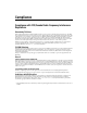
Appendix B Connecting I/O Signals AO0 AOGND0 AO1 AO2 AOGND2 AO3 AO4 AOGND4 AO5 AO6 AOGND6 AO7 NC 1 3 5 7 9 11 13 15 17 19 21 23 25 2 4 6 8 10 12 14 16 18 20 22 24 26 NC NC AOGND1 NC NC AOGND3 NC NC AOGND5 NC NC AOGND7 NC AO 0–7 Connector Pin Assignment AI0+ AIGND0 AI1+ AI2+ AIGND2 AI3+ AI4+ AIGND4 AI5+ AI6+ AIGND6 AI7+ AISENSE 1 3 5 7 9 11 13 15 17 19 21 23 25 2 4 6 8 10 12 14 16 18 20 22 24 26 AI0– AI1– AIGND1 AI2– AI3– AIGND3 AI4– AI5– AIGND5 AI6– AI7– AIGND7 NC AI 0–7 Connector Pin Assignment
Appendix B Connecting I/O Signals NSC68-5050 cable header. In this case, you have access only to the channels that exist on both the SSR backplane and the NSC68-5050 cable header you are using. Figure B-4 shows the connector pinouts when using the NSC68-5050 cable.
Using the SCB-68 Shielded Connector Block C This appendix describes how to connect input and output signals to the NI 783xR with the SCB-68 shielded connector block. The SCB-68 has 68 screw terminals for I/O signal connections. To use the SCB-68 with the NI 783xR, you must configure the SCB-68 as a general-purpose connector block. Refer to Figure C-1 for the general-purpose switch configuration. S5 S4 S3 S1 S2 Figure C-1.
Technical Support and Professional Services D Visit the following sections of the National Instruments Web site at ni.com for technical support and professional services: • Support—Online technical support resources at ni.
Appendix D Technical Support and Professional Services • Calibration Certificate—If your product supports calibration, you can obtain the calibration certificate for your product at ni.com/calibration. If you searched ni.com and could not find the answers you need, contact your local office or NI corporate headquarters. Phone numbers for our worldwide offices are listed at the front of this manual. You also can visit the Worldwide Offices section of ni.
Glossary Symbol Prefix Value p pico 10 –12 n nano 10 –9 µ micro 10 – 6 m milli 10 –3 k kilo 10 3 M mega 10 6 G giga 10 9 Numbers/Symbols ° Degrees. > Greater than. ≥ Greater than or equal to. < Less than. ≤ Less than or equal to. – Negative of, or minus. Ω Ohms. / Per. % Percent. ± Plus or minus. + Positive of, or plus.
Glossary Square root of. +5V +5 VDC source signal. A A Amperes. A/D Analog-to-digital. AC Alternating current. ADC Analog-to-digital converter—An electronic device, often an integrated circuit, that converts an analog voltage to a digital number. AI Analog input. AI Analog input channel signal. AIGND Analog input ground signal. AISENSE Analog input sense signal. AO Analog output. AO Analog output channel signal. AOGND Analog output ground signal.
Glossary C C Celsius. CalDAC Calibration DAC. CH Channel—Pin or wire lead to which you apply or from which you read the analog or digital signal. Analog signals can be single-ended or differential. For digital signals, you group channels to form ports. Ports usually consist of either four or eight digital channels. cm Centimeter. CMOS Complementary metal-oxide semiconductor.
Glossary DIO Digital input/output. DIO Digital input/output channel signal. DMA Direct memory access—A method by which data can be transferred to/from computer memory from/to a device or memory on the bus while the processor does something else. DMA is the fastest method of transferring data to/from computer memory. DNL Differential nonlinearity—A measure in LSB of the worst-case deviation of code widths from their ideal value of 1 LSB. DO Digital output.
Glossary I I/O Input/output—The transfer of data to/from a computer system involving communications channels, operator interface devices, and/or data acquisition and control interfaces. INL Relative accuracy. L LabVIEW Laboratory Virtual Instrument Engineering Workbench. LabVIEW is a graphical programming language that uses icons instead of lines of text to create programs. LSB Least significant bit. M m Meter. max Maximum. MIMO Multiple input, multiple output. min Minimum.
Glossary N noise An undesirable electrical signal—Noise comes from external sources such as the AC power line, motors, generators, transformers, fluorescent lights, CRT displays, computers, electrical storms, welders, radio transmitters, and internal sources such as semiconductors, resistors, and capacitors. Noise corrupts signals you are trying to send or receive.
Glossary R RAM Random-access memory—The generic term for the read/write memory that is used in computers. RAM allows bits and bytes to be written to it as well as read from. Various types of RAM are DRAM, EDO RAM, SRAM, and VRAM. resolution The smallest signal increment that can be detected by a measurement system. Resolution can be expressed in bits, in proportions, or in percent of full scale. For example, a system has 12-bit resolution, one part in 4,096 resolution, and 0.0244% of full scale.
Glossary T THD Total harmonic distortion—The ratio of the total rms signal due to harmonic distortion to the overall rms signal, in decibel or a percentage. thermocouple A temperature sensor created by joining two dissimilar metals. The junction produces a small voltage as a function of the temperature. TTL Transistor-transistor logic. two’s complement Given a number x expressed in base 2 with n digits to the left of the radix point, the (base 2) number 2n – x. V V Volts.